
Page 34 - E BOOK ENGINE MECHANICAL M2
P. 34
5. SERVICE POINTS OF 4B1 ENGINE COMPONENT
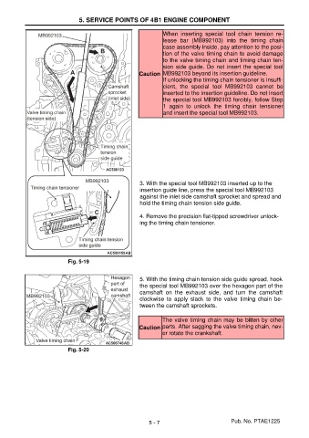
When inserting special tool chain tension re-
lease bar (MB992103) into the timing chain
case assembly inside, pay attention to the posi-
tion of the valve timing chain to avoid damage
to the valve timing chain and timing chain ten-
sion side guide. Do not insert the special tool
Caution MB992103 beyond its insertion guideline.
If unlocking the timing chain tensioner is insuffi-
cient, the special tool MB992103 cannot be
inserted to the insertion guideline. Do not insert
the special tool MB992103 forcibly, follow Step
1 again to unlock the timing chain tensioner
and insert the special tool MB992103.
3. With the special tool MB992103 inserted up to the
insertion guide line, press the special tool MB992103
against the inlet side camshaft sprocket and spread and
hold the timing chain tension side guide.
4. Remove the precision flat-tipped screwdriver unlock-
ing the timing chain tensioner.
Fig. 5-19
5. With the timing chain tension side guide spread, hook
the special tool MB992103 over the hexagon part of the
camshaft on the exhaust side, and turn the camshaft
clockwise to apply slack to the valve timing chain be-
tween the camshaft sprockets.
The valve timing chain may be bitten by other
Caution parts. After sagging the valve timing chain, nev-
er rotate the crankshaft.
Fig. 5-20
5 - 7 Pub. No. PTAE1225