Page 72 - E BOOK ENGINE MECHANICAL M2
P. 72

4. SERVICE POINTS OF 4D56 ENGINE COMPONENT


                                                       6.  Using  the  special  tool  Angle  gauge  (MB991614),
                                                       tighten the connecting rod cap nut in the illustrated se-
                                                       quence by a further 90° to 94°.
                                                             When  the  tightening  angle  is  smaller  than  the
                                                             specified tightening angle, the appropriate tighten-
                                                       Cau- ing capacity cannot be secured.
                                                       tion  When the tightening angle is larger than the speci-
                                                             fied tightening angle, remove the bolt to start from
                                                             the beginning again according to the procedure.

                           Fig. 4-32


                                                       7. Make sure that connecting rod big end side clearance
                                                       meets the specification.
                                                           Standard value: 0.10 - 0.25 mm
                                                           Limit: 0.40 mm


                           Fig. 4-33


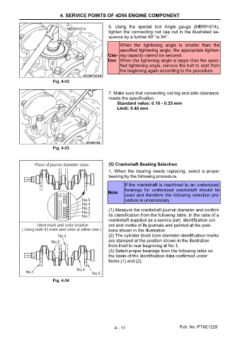
                                                       (5) Crankshaft Bearing Selection
                                                       1.  When  the  bearing  needs  replacing,  select  a  proper
                                                       bearing by the following procedure.
                                                               If the crankshaft is machined to an undersized,
                                                               bearings  for  undersized  crankshaft  should  be
                                                       Note
                                                               used and therefore the following selection pro-
                                                               cedure is unnecessary.

                                                       (1) Measure the crankshaft journal diameter and confirm
                                                       its classification from the following table. In the case of a
                                                       crankshaft supplied as a service part, identification col-
                                                       ors and marks of its journals and painted at the posi-
                                                       tions shown in the illustration.
                                                       (2) The cylinder block bore diameter identification marks
                                                       are stamped at the position shown in the illustration
                                                       from front to rear beginning at No.1.
                                                       (3) Select proper bearings from the following table on
                                                       the basis of the identification data confirmed under
                                                       Items (1) and (2).


                           Fig. 4-34


                                                          4 - 11                          Pub. No. PTAE1228
   67   68   69   70   71   72   73   74