Page 70 - E BOOK ENGINE MECHANICAL M2
P. 70

4. SERVICE POINTS OF 4D56 ENGINE COMPONENT


           (2) Cylinder Head Bolt Installation
                        Before installing the cylinder head bolt, check the number of punch marks on its head.
                        (the bolt is reusable if it is four or less.) the number of punch marks corresponds to that
           Caution
                        to times the bolt has been tightened to the plastic area. if the bolt has five punch marks,
                        replace it.


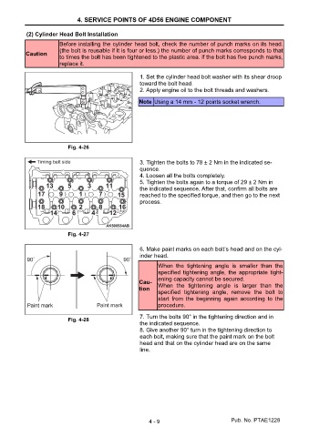
                                                       1. Set the cylinder head bolt washer with its shear droop
                                                       toward the bolt head.
                                                       2. Apply engine oil to the bolt threads and washers.

                                                       Note Using a 14 mm - 12 points socket wrench.


                           Fig. 4-26

                                                       3. Tighten the bolts to 78 ± 2 Nm in the indicated se-
                                                       quence.
                                                       4. Loosen all the bolts completely.
                                                       5. Tighten the bolts again to a torque of 29 ± 2 Nm in
                                                       the indicated sequence. After that, confirm all bolts are
                                                       reached to the specified torque, and then go to the next
                                                       process.


                           Fig. 4-27

                                                       6. Make paint marks on each bolt’s head and on the cyl-
                                                       inder head.
                                                              When  the  tightening  angle  is  smaller  than  the
                                                              specified  tightening  angle,  the  appropriate  tight-
                                                              ening capacity cannot be secured.
                                                       Cau-
                                                       tion   When  the  tightening  angle  is  larger  than  the
                                                              specified  tightening  angle,  remove  the  bolt  to
                                                              start  from  the  beginning  again  according  to  the
                                                              procedure.

                                                       7. Turn the bolts 90° in the tightening direction and in
                           Fig. 4-28
                                                       the indicated sequence.
                                                       8. Give another 90° turn in the tightening direction to
                                                       each bolt, making sure that the paint mark on the bolt
                                                       head and that on the cylinder head are on the same
                                                       line.


                                                          4 - 9                           Pub. No. PTAE1228
   65   66   67   68   69   70   71   72   73   74