
Page 68 - E BOOK ENGINE MECHANICAL M2
P. 68
4. SERVICE POINTS OF 4D56 ENGINE COMPONENT
8. Using the special tool Angle gauge (MB991614),
tighten the injector holder bolt in the illustrated se-
quence by a further 120 to 125°.
Fig. 4-19
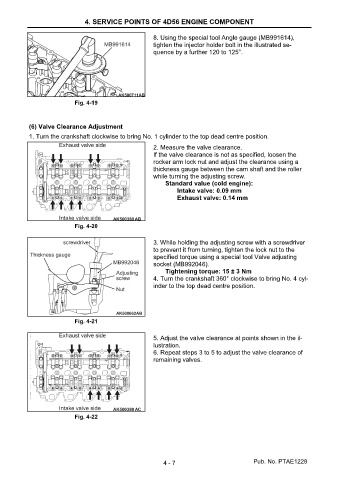
(6) Valve Clearance Adjustment
1. Turn the crankshaft clockwise to bring No. 1 cylinder to the top dead centre position.
2. Measure the valve clearance.
If the valve clearance is not as specified, loosen the
rocker arm lock nut and adjust the clearance using a
thickness gauge between the cam shaft and the roller
while turning the adjusting screw.
Standard value (cold engine):
Intake valve: 0.09 mm
Exhaust valve: 0.14 mm
Fig. 4-20
3. While holding the adjusting screw with a screwdriver
to prevent it from turning, tighten the lock nut to the
specified torque using a special tool Valve adjusting
socket (MB992046).
Tightening torque: 15 ± 3 Nm
4. Turn the crankshaft 360° clockwise to bring No. 4 cyl-
inder to the top dead centre position.
Fig. 4-21
5. Adjust the valve clearance at points shown in the il-
lustration.
6. Repeat steps 3 to 5 to adjust the valve clearance of
remaining valves.
Fig. 4-22
4 - 7 Pub. No. PTAE1228