
Page 69 - E BOOK ENGINE MECHANICAL M2
P. 69
4. SERVICE POINTS OF 4D56 ENGINE COMPONENT
2. ENGINE OVEHAUL
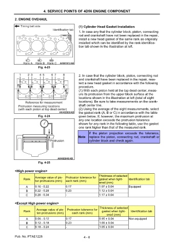
(1) Cylinder Head Gasket Installation
1. In case any that the cylinder block, piston, connecting
rod and crankshaft have not been replaced in the repair,
install a new head gasket of the same rank as originally
installed which can be identified by the rank identifica-
tion tab shown in the illustration at left.
Fig. 4-23
2. In case that the cylinder block, piston, connecting rod
and crankshaft have been replaced in the repair, rese-
lect a new head gasket in accordance with the following
procedure.
(1) With each piston held at the top dead center, meas-
ure its protrusion from the upper block surface at the
locations shown in the illustration at left (total of eight
locations). Be sure to take measurements on the crank-
shaft center line.
(2) Using the average of the eight measurements, select
the gasket rank (A, B or C) in accordance with the table
Fig. 4-24 given below. If, however, the maximum protrusion at
any one location exceeds the protrusion tolerance
shown for any rank in the following table, use the gasket
one rank higher than that of the measured rank.
If the piston projection exceeds the tolerance,
Note replace the piston, connecting rod, crankshaft or
cylinder block and check again.
Fig. 4-25
<High power engine>
Thickness of selected
Average value of pis- Protrusion tolerance for
Rank gasket when tight- Identification tab
ton protrusions (mm) each rank (mm)
ened (mm)
A 0.16 - 0.22 0.17 1.07 ± 0.04 Equipped
B 0.22 - 0.28 0.23 1.12 ± 0.04
C 0.28 - 0.34 - 1.17 ± 0.04
<Except High power engine>
Thickness of selected
Average value of pis- Protrusion tolerance for
Rank gasket when tight- Identification tab
ton protrusions (mm) each rank (mm)
ened (mm)
A 0.06 - 0.12 0.17 0.95 ± 0.04 Non-equipped
B 0.12 - 0.18 0.23 1.00 ± 0.04
C 0.18 - 0.24 - 1.05 ± 0.04
Pub. No. PTAE1228 4 - 8