Page 71 - E BOOK ENGINE MECHANICAL M2
P. 71

4. SERVICE POINTS OF 4D56 ENGINE COMPONENT


                                                       (3) Assembly of Connecting Rod and Piston
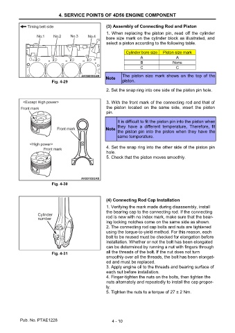
                                                       1. When replacing  the piston  pin,  read  off the cylinder
                                                       bore size mark on the cylinder block as illustrated, and
                                                       select a piston according to the following table.

                                                                 Cylinder bore size   Piston size mark
                                                                        A                 A
                                                                        B                None
                                                                        C                 C
                                                               The  piston  size  mark  shows  on  the  top  of  the
                                                       Note
                           Fig. 4-29                           piston.

                                                       2. Set the snap ring into one side of the piston pin hole.


                                                       3. With the front mark of the connecting rod and that of
                                                       the  piston  located  on  the  same  side,  insert  the  piston
                                                       pin.

                                                             It is difficult to fit the piston pin into the piston when
                                                             they  have  a  different  temperature,  Therefore,  fit
                                                       Note
                                                             the piston pin into the piston when they have the
                                                             same temperature.


                                                       4. Set the snap ring into the other side of the piston pin
                                                       hole.
                                                       5. Check that the piston moves smoothly.


                           Fig. 4-30


                                                       (4) Connecting Rod Cap Installation

                                                       1. Verifying the mark made during disassembly, install
                                                       the bearing cap to the connecting rod. If the connecting
                                                       rod is new with no index mark, make sure that the bear-
                                                       ing locking notches come on the same side as shown.
                                                       2. The connecting rod cap bolts and nuts are tightened
                                                       using the torque-to-yield method. For this reason, each
                                                       bolt to be reused must be checked for elongation before
                                                       installation. Whether or not the bolt has been elongated
                                                       can be determined by running a nut with fingers through

                           Fig. 4-31                   all the threads of the bolt. If the nut does not turn
                                                       smoothly over all the threads, the bolt has been elongat-
                                                       ed and must be replaced.
                                                       3. Apply engine oil to the threads and bearing surface of
                                                       each nut before installation.
                                                       4. Finger-tighten the nuts on the bolts, then tighten the
                                                       nuts alternately and repeatedly to install the cap proper-
                                                       ly.
                                                       5. Tighten the nuts to a torque of 27 ± 2 Nm.


           Pub. No. PTAE1228                              4 - 10
   66   67   68   69   70   71   72   73   74