
Page 156 - Digital Electronics by harish
P. 156
5.4 I/O Mapping and Interrupts
5.4.1 I/O Mapping schemes
I/O interfacing
There are two methods of interfacing the Input / Output devices with the
microprocessor. They are,1) Memory mapped I/O and 2) I/O mapped I/O.
5.4.1.1 Memory mapped I/O
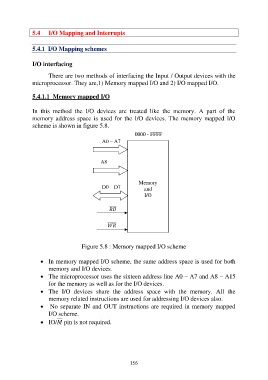
In this method the I/O devices are treated like the memory. A part of the
memory address space is used for the I/O devices. The memory mapped I/O
scheme is shown in figure 5.8.
0000 - FFFF
A0 – A7
A8 –
A15
Memory
D0 – D7 and
A15 I/O
Figure 5.8 : Memory mapped I/O scheme
In memory mapped I/O scheme, the same address space is used for both
memory and I/O devices.
The microprocessor uses the sixteen address line A0 – A7 and A8 – A15
for the memory as well as for the I/O devices.
The I/O devices share the address space with the memory. All the
memory related instructions are used for addressing I/O devices also.
No separate IN and OUT instructions are required in memory mapped
I/O scheme.
IO/ pin is not required.
156