
Page 152 - Digital Electronics by harish
P. 152
The status signals are changed as IO/ = 0, S1
3. =0 and S0 = 1. These status signals do not change
throughout the memory write machine cycle.
4. The microprocessor makes the line LOW to
T enable memory write.
2
5. The contents of the specified register are placed
on the address / data bus.
The data placed on the address / data bus is
6. transferred to the specified memory location.
T
3
7. The microprocessor makes the line HIGH to
disable the memory write operation.
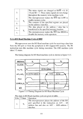
5.3.1.4I/O Read Machine Cycle of 8085
Microprocessor uses the I/O Read machine cycle for receiving a data byte
from the I/O port or from the peripheral in I/O mapped I/O systems. The IN
instruction uses this machine cycle during execution. The IOR machine cycle
takes 3 T-states.
The timing diagram for I/O Read machine cycle is shown in figure 5.13.
Figure 5.13 Timing Diagram for I/O Read Machine Cycle
The steps in I/O Read machine cycle are given in table.
S.No T State Operation
The microprocessor places the address of the I/O
port specified in the instruction on A15 – A8
1. T address bus and also on AD7 – AD0 address /
1
data bus.
152