
Page 702 - CarrLaneCatalog_2019ed-c.pdf
P. 702
Hydraulic Intensifier 7250 psi max
APPLICATION: The hydraulic intensifier high-pressure is obtained, pulsation of the
converts a hydraulic pressure on the primary intensifier is stopped. Pulsation continues in
side (input) into a higher pressure on the case of dynamic application. Max. frequency
secondary side (output). of pulsation is 30 Hz.
This enables the use of the comparatively To retract the cylinder, the internal check valve
low pressure of machine tool hydraulics DV is controlled via port R and thereby free
to pressurize a hydraulic cylinder with a return through the intensifier is guaranteed.
correspondingly increased intensification ratio.
IMPORTANT NOTES: The hydraulic oil must
DESCRIPTION: The construction of the be perfectly filtered with particles not larger than
hydraulic intensifier corresponds to the nominally 10 micron. This is the reason why
principle of pressurizing areas of different we offer a filter unit (part no. CLR-3887-087),
sizes. Regulation of the high pressure at the which can be directly integrated in the tubing
secondary side is made by regulation of the of the low-pressure side. If the intensifier will
low pressure side and is directly proportional. be used on uncoupled systems (no connection
to the pressure generator) a pilot-controlled
First the intensifier delivers a high flow rate at check valve should be mounted at the high-
a low pressure (displacement of the cylinders), pressure side (consider min. control pressure
with increasing counterpressure the for opening). For pilot-operated check valve,
intensifier switches automatically to pressure see valves section.
intensification. For unclamping, the cylinder is
directly controlled with the low-pressure of the When designing an installation, pay attention
primary side (see example on previous page). that there can be leakage between the ports IN
and R of the high-pressure intensifier.
FUNCTION: the oil is supplied through input
IN via the check valves RV1, RV2, and DV Leakage rate approx. 50 cm3/min. When
to the high pressure output H and thereby to using the intensifier in uncoupled systems
the cylinders. In this phase the intensifier is in there will be a pressure increase in the
rapid function. According to the in ten sification unclamping line due to the leakage. — Please
i the max. flow rate can be up to 10 liters/ contact us.
min. With increasing pressure in the cylinder
the oscillating pump unit OP (pulsation)
automatically functions. If the adjusted
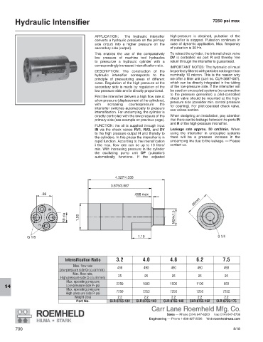
G 1/4
Intensification Ratio 3.2 4.0 4.8 6.2 7.5
Max. flow rate
490 490 490 490 490
Low-pressure side Q IN (cu.in/min)
Max. flow rate,
25 25 25 25 25
High pressure side Q H (cu.in/min)
Max. operating pressure
2250 1800 1500 1100 950
Low-pressure side P IN psi
14
Max. operating pressure
7250 7250 7250 7250 7250
High-pressure side P H psi
Weight (lbs) 2.2 2.2 2.2 2.2 2.2
Part No. CLR-8755-132 CLR-8755-140 CLR-8755-148 CLR-8755-162 CLR-8755-175
Carr Lane Roemheld Mfg. Co.
Sales — Phone (314) 647-6200 Fax (314) 647-5736
Engineering — Phone 1-800-827-2526 Web roemheld-usa.com
700 8/18