
Page 66 - test2
P. 66
IV. Possible Flow Paths
The Panel identified three possible paths by which hydrocarbons could
have flowed up the well to the rig during the initial stage of the blowout: (1) up
the production casing annulus cement barrier and upward through the annulus
and the wellhead seal assembly; (2) up the production casing and related
151
components from above the top wiper plug located on the float collar at 18,115
feet; or (3) up the last 189 feet of the production casing (the “shoe track”).
Scenario 1: Production Casing Annulus Cement Barrier and the Wellhead Seal
Assembly
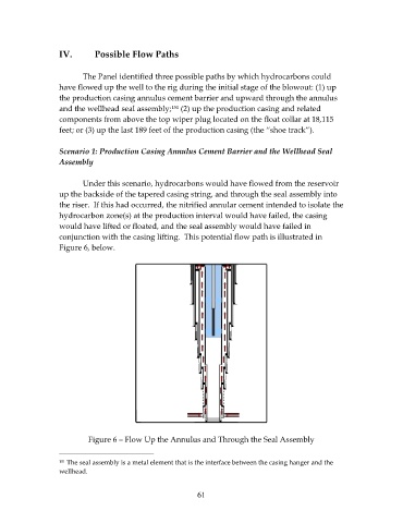
Under this scenario, hydrocarbons would have flowed from the reservoir
up the backside of the tapered casing string, and through the seal assembly into
the riser. If this had occurred, the nitrified annular cement intended to isolate the
hydrocarbon zone(s) at the production interval would have failed, the casing
would have lifted or floated, and the seal assembly would have failed in
conjunction with the casing lifting. This potential flow path is illustrated in
Figure 6, below.
Figure 6 – Flow Up the Annulus and Through the Seal Assembly
151 The seal assembly is a metal element that is the interface between the casing hanger and the
wellhead.
61