
Page 121 - Robot Design Handbook ROBOCON Malaysia 2019
P. 121
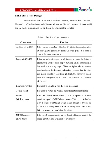
2.2.2 Electronic Design


                         The electronic circuit and controller are based on components as listed in Table 1.
                  The motion of the legs is controlled by the micro-controller and photoelectric sensors [7],

                  and the modes of operations can be chosen by activating the switches.


                                            Table 1: Function of the components

                        Component                                    Function

                   Arduino Mega 2560       It is a micro-controller which has 54 digital input/output pins,

                                           16 analog input pins and 4 hardware serial ports. It is used to
                                           control the robot movement.


                   Panasonic CX-422        It is a photoelectric sensor which is used to detect the distance,

                                           presence or absence of an object by using a light transmitter. It
                                           has maximum sensing range of 800mm. 4 photoelectric sensors

                                           are placed near the legs to synchronise 4 legs so that the robot
                                           can  move  smoothly.  Besides  a  photoelectric  sensor  is  placed

                                           near  the Gerege holder  to  scan  the  absence  or  presence
                                           of Gerege.


                   Emergency switch        It is used to operate or stop the robot movement.

                   Toggle switch           It is used to switch the walking mode for autonomous robot.


                   Power                   It is a DC motor which require 12VDC to operate it. It has a
                   Window motor            maximum speed of 60RPM and torque of 30kgf.cm. It also has

                                           a break torque of 100kg.cm which is high enough to prevent the
                                           robot from moving when it is at stationary state. Four Power

                                           Window motor are installed on four legs.

                   MDD10A motor            It is a dual channel motor driver board which can control the

                   driver board            speed, direction and activation of DC motor.


                                                            117