
Page 153 - Robot Design Handbook ROBOCON Malaysia 2019
P. 153
The mechanical division of the team focuses on the design, prototyping and manufacturing
of the thrower, robotic arm and supporting truss for both robots.
2.1.1 The Robots
Slider
Thrower
Gripper
Sprocket
Chain
(a) (b)
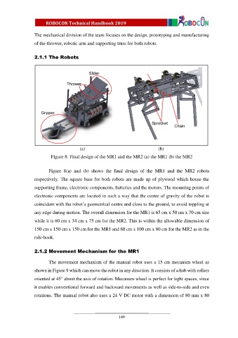
Figure 8: Final design of the MR1 and the MR2 (a) the MR1 (b) the MR2
Figure 8(a) and (b) shows the final design of the MR1 and the MR2 robots
respectively. The square base for both robots are made up of plywood which house the
supporting frame, electronic components, batteries and the motors. The mounting points of
electronic components are located in such a way that the centre of gravity of the robot is
coincident with the robot’s geometrical centre and close to the ground, to avoid toppling at
any edge during motion. The overall dimension for the MR1 is 65 cm x 50 cm x 70 cm size
while it is 60 cm x 34 cm x 75 cm for the MR2. This is within the allowable dimension of
150 cm x 150 cm x 150 cm for the MR1 and 80 cm x 100 cm x 80 cm for the MR2 as in the
rule-book.
2.1.2 Movement Mechanism for the MR1
The movement mechanism of the manual robot uses a 15 cm mecanum wheel as
shown in Figure 9 which can move the robot in any direction. It consists of a hub with rollers
oriented at 45° about the axis of rotation. Mecanum wheel is perfect for tight spaces, since
it enables conventional forward and backward movements as well as side-to-side and even
rotations. The manual robot also uses a 24 V DC motor with a dimension of 80 mm x 80
149