
Page 155 - Robot Design Handbook ROBOCON Malaysia 2019
P. 155
2.1.4 Throwing Mechanism for the MR1
The throwing mechanism for the MR1 consists of a gripper, a slider, and a thrower,
each attached to a pneumatic system for actuation as shown in Figure 8 (a). The Shagai
throwing sequence starts with holding, lifting, and putting the Shagai into the slider which
is carried out by the programmed gripper mechanism. The gripper consists of cables, spring
and a pneumatic system. The function of the cable is to connect the gripper with the
pneumatic components, while the spring is used to limit the opening and closing of the
gripper. The slider consists of a pillow bearing and a pneumatic system within the
mechanism to turn the robotic arm and put the Shagai on the slider. The pneumatic system
for gripper has dimensions of 50 mm stroke and 20 mm bore size and is a mechanism that
is used to push the Shagai. After the slider receives the Shagai, it will extend its length
forward before the thrower starts throwing the Shagai into Landing Zone. It uses two
pneumatic systems to push the slider forward and push the Shagai into landing area, each
with dimensions of 200 mm and 20 mm bore size. All pneumatic systems used are operated
with pneumatic cylinder with maximum pressure of five bars and connected to solenoid
valve with 1-7 bars operating pressure range, as well as a set of soda bottles for the pressure
tank.
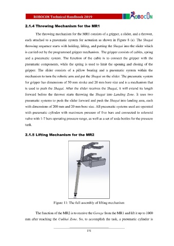
2.1.5 Lifting Mechanism for the MR2
Figure 11: The full assembly of lifting mechanism
The function of the MR2 is to receive the Gerege from the MR1 and lift it up to 1000
mm after reaching the Uukhai Zone. So, to accomplish the task, a pneumatic cylinder is
151