
Page 23 - Robot Design Handbook ROBOCON Malaysia 2019
P. 23
2.0 DETAILED DESIGN
2.1 Mechanical Design
There are three main mechanical mechanisms needed to develop the manual and
auto robot. These sare the driving, lifting and pushing mechanisms.
For a manual robot, it uses all three types of mechanism. The robot is driven by four
self-design wheels and uses differential drive mechanism for turning purposes. The wheels
always rotate at the same speed according to the PWM supplied by the micro-controller. All
the moving-purpose wheels are powered by a DC gear motor A585W (12 V, 160 rpm). The
wheel motors get signals from the micro-controller based on the feed-back from the sensor.
The differential drive will continue turning the machine until it is aligned with the white
line. The speed of the robot can be changed by increasing or decreasing the percentage of
PWM that are given to the motors of the wheels. For lifting mechanism, we control the
motor that is connected to a pulley in order to lift up the Shagai holder. Lastly, for pushing
mechanism in the manual robot, a pusher is designed to push out the Shagai to the Landing
Zone. Sling-shot concept is used to provide force for the pusher to push the Shagai.
For the auto-robot, only the driving mechanism was used. As stated in the rule-book,
the robot was designed as a legged robot. We have selected the Plantigrade mechanism as
the leg mechanism. Each leg of the robot was built by joining various joints and links. The
movement of the robot is controlled by a motor that is connected to one of the links on the
leg. Thus, when the motor gets a signal to rotate, the leg will move.
To pass the Gerege from the MR1 to the MR2, a motor will rotate the Gerege holder
in the MR1 to certain degrees in order for it to be in contact with the slider holder in the
MR2. The Gerege will slide through the slider and then into the holder slot.
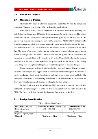
2.1.1 Design Specification
Table 1: Design Specification
SPECIFICATIONS MANUAL ROBOT (MR 1) AUTO-ROBOT the MR2
Dimensions (mm) 500x1100x900 850x550x750
Mass (kg) 15 15
Payload Capacity (kg) 5 3
Material Aluminium + PLA Aluminium + PLA
19