Page 129 - APPLIED PROCESS DESIGN FOR CHEMICAL AND PETROCHEMICAL PLANTS, Volume 1, 3rd Edition
P. 129

Fluid Flow                                           113


            80                                                                  ,               ,
                                               J                 IJ                       J          J   "
            50                                I/          [/  I   II   IJ                      I    f
            40                               1,    I,          J   ,   I,    C7  7     ,  I/   I/   ,  I  '
                                                         '
                                            1,          f
            30                                    '    I         I,   IJ    I         11    11        I
                                          I/    I     I/    II  '          I         II    J    I   J
            20                                       �               '  ,
                                         )     ,  J        )              I/        J    I    I     II
          ti:  1 S                      v           �     v   v   v                           11
          0                            I                                          ll    ll   �   I/
          0   10                             1,    LJ    '   J                        ,
                                                                                         \\ - Ii  ,,  ,
                                      I  I   ,,--1 --,,   ,  I  I   I            I
                                                          �  '
         i  8.0                    :.J -    -  t-t- �    L-   ;.. '/- ;;."l- -:,r  ._,.i   l7   �.t'.J  �  �J  -�  7
                                                                'J
                                                                             �I
         g 5.0                           .::.1  - ....   v          I        17    I             I
                                               I
                                 �
         .,,                    � .   /   r  J   "     ,  ,  J   ,   ,  J   -.    ,     '    I,
         ': 4.0
                                                                                  --..
         s 3.0                 �       J     v     J   I    I/   ,,        I  I       17   IJ
          I                    �      I/    I     I   II'   I             I     I
                                                           '
         e,  2.0               II'                       II                          '    J
         0                           )    II    I               I              J        J        l
         �  i.s               II'                                       �    v          'I'
         w                   I     I     j    I/   II   I     I        J          II   I
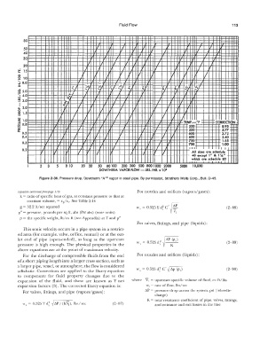
         �  1.?                                   '    I     /                          TEMP.  •F      CORRECTION
         �  0.8            I          ,  I       I                         ,  I  I   I
         w                       J          IJ             J                              500             8.95:
         "'  0.5                               J          I         I          J          550             5.77-
         .....
                                                                                                          3.72  -
                                                                                          600
           0.4           J          J     I   I/   I      r       ,  J   J    I   I/      650             2.40   �
                              I     r             J      J              J        ,
            0.3        I     I    r  I   II'  I   IJ   I  I      ,          I   I         700             1.55
                                                                                          750
                                                                                                          1.00
                                       I
                                                                               J
           0.2      v  J   I          I   r   I/     �  I/     I)    1,   ,  I  I/        I  11          I   I   ....
                                                                                           All  sizes  are  schedule
                                                               J
                                                                    J
                                                                                           40  except  1" &  1  'A"   ....
                                                                                                       .
                                                                                           which  are  schedule  80
                    2   3       8  10   20  30   50  80 100   200  300  500  800 1000  2000   5000   10,000
                                                DOWTHERM  VAPOR FLOW -  LBS./HR. x  10 2
                    Figure 2-36.  Pressure drop,  Dowtherm "A"® vapor in steel pipe.  By permission, Struthers Wells Corp., Bull.  D-45.
         (equation  continuedfrom pag,:  110)                     For nozzles and orifices  (vapors/gases):
           k =  ratio of specific  heat of gas,  at constant pressure to that at
              constant volume,  =  cp/c,  ..  See Table 2-14
           g  =  32.2 ft/sec squared                             w,  =  0.525Yd c' �                        (2-88)
                                                                   '
                                                                             2
                                                                              '  {V:-
          p" = pressure, pounds per sq ft, abs  (Psf abs)  (note units)
           p  =  the specific weight,  lb/cu ft  (see Appendix)  at T and p"
                                                                  For valves,  fittings,  and pipe  (liquids):
            This sonic velocity occurs in a pipe system in a restrict-
         ed area (for example, valve, orifice, venturi)  or at the out-
         let end  of pipe  (open-ended),  as  long  as  the  upstream   .  =  0 52- d2   /!lP   (P1)
         pressure  is  high  enough.  The  physical  properties  in  the   '\ s   .   !J   i  I   K         (2-89)
         above  equations are at the point of maximum velocity.
            For the  discharge  of compressible  fluids from  the end   For nozzles and orifices  (liquids):
         ofa short piping length into a larger cross section, such as
         a larger pipe, vessel, or atmosphere,  the flow is considered
         adiabatic.  Corrections are  applied  to  the  Darcy  equation   w,  =  o.s2s d�  c'  � lip  (p 1)   (2-90)
         to  compensate  for  fluid  property  changes  due  lo  the
         expansion  of the  fluid,  and  these  are  known  as  Y net   where  V  1  =  upstream specific volume of fluid, cu ft/lbs
         expansion factors  [3]. The corrected Darcy equation is:     w,  =  rate of flow,  lbs/sec
            For valves,  fittings,  and pipe  (vapors/gases):        Af>  =  pressure drop across the system,  psi  (inlet-dis-
                                                                          charge)
                                                                      K =  total  resistance coefficient of pipe, valves,  fittings,
            w,  =  0.525Ydf  � P/(KYi),   lbs/sec     (2-  87)            and entrance and exit losses in the line
   124   125   126   127   128   129   130   131   132   133   134