Page 197 - APPLIED PROCESS DESIGN FOR CHEMICAL AND PETROCHEMICAL PLANTS, Volume 1, 3rd Edition
P. 197

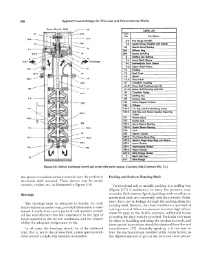
168                       Applied Process Design for Chemical  and Petrochemical  Plants

                                                                                         PARTS  LIST
                                                                             Cat.
                                                                             No.            Part Name
                                                                              2-F   First Stage Impeller
                                                                              2-S   Second Stage Impeller and Above
                                                                             34   Nozzle Head Bushing
                                                                            260   Diffuser Ring
                                                                            298   Suction Bell  Ring
                                                                              8   Stvfflng Box lushing
                                                                              9-L   Lower Shaft Sleeve
               Inlet
                                                                              9.1   Intermediate Shaft SIHve
                                                                              9-U  Upper Shaft SIHve
                  910                                 34                     12   Packing
                                                                             13   Seal  Cage
                                                                             14   Gland
                  2.57·1                              171                    14-A  Gland  Bolt
                                                                             31   Complete Coupling
                                                                             61-P   Pump Half Coupling Lock Nut
                  223                                 7                      61-M  Motor Half Coupling  Loclc  Nut
                                                                             62   Complete Piping
                                                                             73   Stuffing  Box
                  218                                                        89   Ba  lance Disk
                                                                            140   Motor Support Column
                                                                            146   Diffuser
                  2-S                                                       162-F   ht.  Stg. Impeller Retaining  Collar
                                                                            162-S   2nd  Stg. and Above  Impeller Retaining
                                                                                  Collar
                 162·5                                                      171   Nozzle Head
                                                                            175   Sudion  llell
                                                                            190-L   lower Sleeve Bearing
                  U6                                 190-U                  190-U  Upper Sleeve Bearing
                                                                            218   Tank
                                                                            223   Spacer Column
                 237-F                                162-f                 237-F   First Stage Snap Ring
                                                                            237-S   Second Stage Snap Ring and Above
                                                                            257-L   Lower Gasket
                  190-L                               298                   257-1   lntennedlate Gasket
                                                                            257-U  Upper Gasket
                                                                            257-S   llllnd  Flange Gasket
                                                                              7   Shaft with Keys
                  175
                                                                            910   lllnd flange
                            Figure 3-9. Vertical  multistage centrifugal  pump with barrel  casing. (Courtesy Allis-Chalmers Mfg.  Co.)


              the proper corrosion resistant material over the preferred   Packing and Seals on Rotating Shaft
              structural  shaft  material.  These  sleeves  may  be  metal,
              ceramic,  rubber,  etc., as illustrated in Figure  3-16.   Conventional  soft  or metallic packing in a stuffing box
                                                                    (Figure  3-17)  is  satisfactory  for  many  low  pressure,  non-
              Bearings                                              corrosive fluid systems.  Special  packings such as teflon, or
                                                                    mechanical  seals  are  commonly used for corrosive fluids,
                                                                    since there can be leakage through  the  packing along the
                The  bearings  must be  adequate  to  handle  the  shaft
              loads without excessive wear,  provided lubrication is main-   rotating shaft.  However,  for these conditions a mechanical
                                                                    seal is preferred. When the pressure becomes high  (above
              tained.  Usually  this is not a point of real question provid-   about 50  psig)  or the fluid  is  corrosive,  additional  means
              ed the  manufacturer has  had  experience  in  the  type  of   of  sealing the shaft must be provided.  Particular care must
              loads  imposed by  the service conditions,  and the respon-   be taken  in handling and using the mechanical  seals, and
              sibility for adequate design  must be his.
                                                                    these special instructions should be obtained from the seal
                In  all  cases,  the  bearings  should  be  of the  outboard   manufacturer  [27].  Generally  speaking  it is  not wise  to
              type, that is, not in the process fluid, unless special  condi-   have the mechanical  seal installed at the pump factory,  as
              tions  prevail to make this situation acceptable.     the slightest amount of  grit on the faces can cause perma-
   192   193   194   195   196   197   198   199   200   201   202