
Page 201 - APPLIED PROCESS DESIGN FOR CHEMICAL AND PETROCHEMICAL PLANTS, Volume 1, 3rd Edition
P. 201
172 Applied Process Design for Chemical and Petrochemical Plants
The "single" mechanical seal is made of a rotating ele- used under various conditions 111 the wide variety of
ment fixed to the shaft (or shaft sleeve), and a stationary process fluids.
element fixed to the pump casing [16]. The average unbalanced external seal is good for pres-
The "double" seal is for severe sealing problems where sures of about 30 psig, while the balanced design will han-
out-leakage to the environment cannot be tolerated and dle 150 psig. Special designs will handle much higher
must be controlled. (See Figures 3-31C and 3-310.)
Depending upon the fluid's characteristics, the vent
Flush
between the double seals (Figures 3-31A and B) may be Gland connection
gas�et
purged with process liquid, or a different liquid or oil, or
it may be connected to a seal pot and vent collection to Drive pi,n Gland
prevent leakage to the air/ environment. There are tech- Stuffing-box $ring
housing ',,
niques for testing for leakage of the inner seal by measur- '
ing the vent space pressure through the seal liquid surge '
port. This should be essentially atmospheric (depending
on the vent system backpressure). This allows detection
before the leakage breaks through the outer seal.
Figure 3-18 illustrates a seal installed in a conventional
stuffing box with cooling liquid flow path. Figures 3-18, 3-
l9A, 3-198, 3-20 and 3-21 identify the fundamentals of
mechanical seals, even though there are many specific
designs and details. These various designs are attempts to
correct operational problems or seal weaknesses when
I I Primary seal '.
'I
Mechanical-seal , elements )
hardware
-. Secondary seals_,�
e,-� : -- . - =-_]
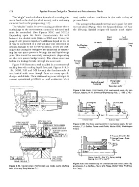
I Ir;;'. , ��� Figure 3-19A. Basic components of all mechanical seals. (By per-
I mission, Adams, W. H., Chemical Engineering Feb. 7, 1983, p. 48.)
· (3) (2)
't Shafi+-·--·--·-·
Internal Seal Exltrnol Seol
SPRING HOLDER
U:H HR M Figure 3-198. The three sealing points in mechanical seals. (By per-
SPRING-18·8 mission, T. J. Sniffen, Power and Fluids, Winter 1958, Worthington
WORK HAR ENED Corp.)
DRIVE COLI AR
L'.:.!.� CHROME.
P: Prtnurt of Liquid in Boa
p':Avtrage Pressure Across
Stol Facts
Closi�g Foret: P 1 1 Arta "A:: t, Spring Loading
Opening Force : P I Arto B
Figure 3-20. Area relationship for unbalanced seal construction. (By
Figure 3-18. Typical single mechanical seal inside pump stuffing permission, T. J. Sniffen, Power and Fluids, Winter 1958, Worthing-
box. (Courtesy Borg-Warner Co.) ton Corp.)