
Page 224 - APPLIED PROCESS DESIGN FOR CHEMICAL AND PETROCHEMICAL PLANTS, Volume 1, 3rd Edition
P. 224
194 Applied Process Design for Chemical and Petrochemical Plants
reads 100 psia vapor pressure. Then follow the slant lines have similar (not necessarily identical) performance char-
(parallel) to read the scale for NPSH reductions, that is, acteristics. The three main characteristics of capacity,
feet at 9.5 ft. head, and rotative speed are related into a single term
Now the pump selected reads NPSHR on its pump per- designated "specific speed" [25]. The expression for spe-
formance curve of 12 feet for cold water service. cific speed is the same whether the pump has a single or
double suction impeller.
Now, ;1 of 12 ft = 6 ft The principle significance of specific speed for the
Figure 3-46 reads = 9.5 ft reduction process engineer is to evaluate the expected performance
Corrected value of NPSHR to use = 6 ft, since 9.5 ft is of a second pump in a particular manufacturer's series
> � the cold water value while basing it on the known performance (or curve) at
the point of optimum efficiency of a first and different
Example 3-11: Alternate to Example 3-10 size pump. In effect the performance of any impeller of a
manufacturer's homologous series can be estimated from
Assume that a boiler feed water is being pumped at 180 the known performance of any other impeller in the
F. Read the chart in Figure 3-46 and the water vapor pres- series, at the point of optimum efficiency. Figures 3-48
0
sure curve, and follow over to read NPSH reduction = and 3-49 represent the standardized conditions of essen-
0.45 feet. A pump selected for the service requires 6 feel tially all pump manufacturers.
cold water service NPSHR:
A typical "operating specific speed" curve is shown
� of 6 = 3 ft in Figure 3-50 and represents a technique for plotting
Value from chart for 180°F = 0.45 ft reduction the specific speed on the operating performance
Then correct NPSHR to use = 6 ft - 0.45 ft = 5.55 ft curve. Figure 3-50 represents a 6-inch pump operating
required by the pump at 1760 rpm, with maximum efficiency at 1480 GPM
for this service and 132 feet head [25]. The operating specific speed is
zero at no flow and increases to infinity at the maxi-
mum flow of 2270 gpm and zero head. Stable opera-
Specific Speed
tions beyond about 1600-1700 gpm cannot be planned
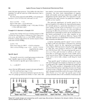
The specific speed of a centrifugal pump correlates the from such a curve with a sharp cutoff drop for head
basic impeller types as shown in Figure 3-47. capacity.
The formula for specific speed index number is: "Type specific speed" is defined as that operating spe-
cific speed that gives the maximum efficiency for a specif-
ic pump and is the number that identifies the pump type
N s = n{Q_/H 3/4 (3-11)
[25]. This index number is independent of the rotative
speed at which the pump is operating, because any change
where: Q is the GPM capacity at speed n in rpm and head H. in speed creates a change in capacity in direct proportion
H is the total head per stage, in feet. and a change in head that varies as the square of the speed
The principle of dynamical similarity expresses the fact [25]. Practice is to "true type" the specific speed of the
that two pumps geometrically similar to each other will pump reasonably close to the conditions of maximum effi-
0 0 0 0 00 0 0 8 0 0 0 0 0 00 0 0
0 0 0 0 00 0 0 0 0 0 0 0 00 0 0
an <D I'- a, a, q, 0 0 q 0 0 00
� <'i ,,; � 0 s ,..:- aS O'i cS' 0 0
iri'
�
0
Values of Specific Speed N
Impeller Shrouds
Radial -Vane Field Mixed- Flow Field Axial-Flow Field
Figure 3-47. Impeller designs and corresponding specific speed range. (By permission, Standards of the Hydraulic Institute, 10th ed.) Also
see [17], Hydraulic Institute, 13th ed., 1975.