Page 229 - APPLIED PROCESS DESIGN FOR CHEMICAL AND PETROCHEMICAL PLANTS, Volume 1, 3rd Edition
P. 229

Pumping of Liquids                                       199

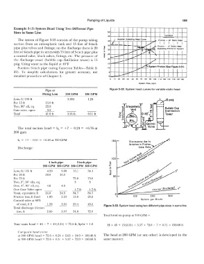
         Example 3-13:  System Head Using Two Different Pipe
         Sizes in Same Line                                       50                               I   I   I
                                                                  45                                Condition
            The system  of Figure  3-53 consists of the  pump taking   40   ,  Impeller  Operating  Head  Curve   ,,,,   ..  Friction  +  22'  Static  Head  _
         suction  from  an  atmospheric  tank and  15 feet of 6-inch   35  lL  .._  -    /       t .r  1__,  __  1  .1_
                                                                                                Friction  +  15'  Static  Head
         pipe  plus valves and fittings;  on the  discharge  there is  20   J   30   -  � ,::;.-  _..-.:::::   Operating  Points  for System
                                                                  20 -
         feel of  4-inch pipe in series with 75 feet of  3-inch pipe plus   .5   �..,..,...   t-  ... t  <,   .   I
         a control valve,  block valves,  fittings,  etc.  The  pressure  of   i  25   :...-  --   .,....,..  ...
                                                               :r
         the  discharge  vessel  (bubble  cap  distillation  tower)  is  15   15  -   �    vi"
                                                                        i.--
         psig.  Using water as the liquid at 40°F
            Suction:  6-inch pipe  (using Cameron Tables-Table 2-   110            ......-   t>  I'"  System Friction (See Figure 3-51)
         22).  To  simplify  calculations  for  greater  accuracy,  use   5   �   .,....,..   I  I  I  I  I  I  I   i
                                                                        �
         detailed procedure of Chapter 2.                         0  -                                           !
                                                                   0   10  20  30  40   50  60  70  80  90  100  110  120  130  uo  150  160
                                                                                    System  Flow,  Gpm.
                            Pipe or                                Figure 3-52. System head curves for variable static head.
                           Fitting Loss   200 GPM   300 GPM
         Loss,  ft/100 ft                0.584        1.24                                           15 psi;
         For 15 ft           15.0 fl
         Two,  900  ell,  eq.   22.8                                         A tmos!)heric          Bubble Cop
         Gate valve,  open   __1,L                                             Vent                 Distillation
         Total              41.0 ft      0.24 ft.     0.51  ft                                      Tower


            The  total  suction head  =  h,  =  +7  - 0.24  =  +6.76 at
         200 gpm

            h, =  +7 ·- 0.51  =  +6.49 at 300 GPM                   150        Discrepancy  due  lo   ....,
                                                                              Variation in  Friction,  .,.,-'
            Discharge:                                                              Lou  Doto.,�
                                                                                          /
                                                                                        .... "  ,it'
                                                                                     1:,
                                                                                   �<t°',"'  ,_,...,\
                                                                                  �....   'ti:,
                                                                    100       x  C:,'\ � ':-_  .,._\ � °''t\CIC)j
                              4 inch pipe      3 inch pipe         ::      -<,o.'°'
                           200 GPM  300 GPM  200 GPM  300 GPM     ....
                                                                   c:
                                                                   ..
         Loss,  ft/  l OC  ft   4.29   9.09   16.1    34.1         "O                                     3"
                                                                   0
         For 20 ft          20.0     20.0                          :I:   50
         For 75 fl                           75.0     75.0
         Two,  3",  90°  ells, eq.            8        8
         One,  4",  90° ell,  eq.   4.6   4.6
                                                                                                  \Oischorgel  .;"
                                                                                            friclion
         One Gate Valve open                  L. 7 fl   1.7 ft        o���==::::::::::::===�
         Total,  equivalent ft   24.6   24.6   84.7   84.7
         Friction loss,  ft fluid   1.06   2.23   i3.6   28.8          0         100       200        300
         Control valve al 60%                                                        Gallons  per  Minute
           of total,  ft  fl   1.59   3.34   20.4     43.2     Figure 3-53. System head using two different pipe sizes in same line.
         Total discharge friction
           loss, ft          2.65     5.57   34.0     72.0
                                                               Total head on pump at 300 GPM  =
         Total static head= 45  - 7  +  15(2.31)  =  72.6 ft,  SpGr =  1.0   H =  45  +  15(2.31)  +  5.57  +  72.0  - 7  +  0.51  =  150.68 ft

            Composite head curve
            at 200 GPM:  head  = 72.6  +  0.24  +  2.65  +  34.0  =  109.49 ft   The  head at 200 GPM  (or any  other)  is developed in the
            at 300 GPM:  head  =  72.6  +  0.51  +  5.57  +  72.0  =  150.68 ft   same manner.
   224   225   226   227   228   229   230   231   232   233   234