
Page 244 - APPLIED PROCESS DESIGN FOR CHEMICAL AND PETROCHEMICAL PLANTS, Volume 1, 3rd Edition
P. 244
214 Applied Process Design for Chemical and Petrochemical Plants
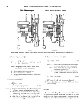
DIM Diaphragm FLOWS TO 1480 GPH, PRESSURES TO 5000 PSI
SUCTION DISCHARGE
Figure 3-65A. Diaphragm metering pump, "Pulsa" series. One of several styles/types. (By permission, Pulsafeeder, Inc.)
(c) Liquid displacement [6]: 3. Pump power output (whp) [ 17]
d "(1 - En) whp, = (Q'P,ct)/1714 (3-45)
d'= ----------, cu ft/min (3-43;
(1 - E 11) + E,, (P/P 1)
where P,d = differential pressure between absolute pres-
where P is theatmospheric pressure, and P 1 is the sures at the outlet and inlet to pump, psi
inlet absolute pressure to the pump. whp, = power imparted by the pump to the fluid
discharged (also liquid HP)
d"= theoretical displacement, cu ft/min Ev = volumetric efficiency, ratio of actual pump
d' = liquid displacement, cu ft/min capacity to the volume displaced/unit time
En= percent entrained gas by volume at atmospheric
pressure E,. = 231 Q'(lOO)/(D"n) (3-46)
2. Volume displaced [ 17]
4. BHP varies directly with pressure and speed.
5. For speed and pressure constant, BHP varies direct-
Q' = D "n - S" GPM ly with viscosity.
231 '
(for no vapor or gas present ) (3- 44)
where Q' = capacity of rotary pump, fluid plus dissolved gases/ Selection
entrained gases, at operating conditions, GPM
D" = displacement (theoretical) volume displaced per
revolution (s) of driving rotor, cu in./revolution Suction and discharge heads are determined the same
n = speed, revolutions per minute of rotor(s), rpm as for centrifugal pumps. Total head and capacity are used
S" = slip, quantity of fluid that leaks through internal in selecting the proper rotary pump from a manufactur-
clearances of pump per unit time, GPM er's data or curves. Since viscosity is quite important in the