
Page 242 - APPLIED PROCESS DESIGN FOR CHEMICAL AND PETROCHEMICAL PLANTS, Volume 1, 3rd Edition
P. 242
212 Applied Process Design for Chemical and Petrochemical Plants
through V-belts or gears. The pump manufacturer should
know the preferred type of drive. If the manufacturer is to Water Vertical Pumps
furnish the driver, the data on the specification sheet Flow
under Driver should be completed as far as applicable. If
a gas or gasoline engine is to be used, the type of fuel and
its condition must be stated. Engine cooling water (if air d=Bd/3
not used) must be specified.
Sump Design for Vertical Lift
Partition
The proper design of sumps for the use of vertical lift (see Ref. [17])
pumps or horizontal pumps taking suction from a sump
is important to good suction conditions at the pump [2,
3, 14].
The arrangement and dimensions indicated in Figure
3-62 or Figure 3-63 are satisfactory for single or multiple 0
pump installations. (For more details, refer to Reference
[17]). A few key points in sump-pump relationships for
good non-vortexing operation are:
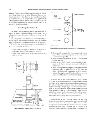
Figure 3-63. Acceptable sump arrangement for multiple pumps.
1. Avoid sudden changes in direction or elevation of
flow closer than five bell diameters to pump.
2. Avoid sump openings or projections in water path 3. Have water flowing parallel to sump walls as it enters
close to pump. pump. Water should enter pump suction with as low
a turbulence as possible.
4. Water velocity in sump must be low, 1J4 feel/second
is good practice.
- 5. Inlet channel width to each pump is considered opti-
mum at 2 Bct to prevent secondary turbulence
effects. [3]
6. Avoid placing several pumps in one open channel
--- removing water in series fashion. If this must be
done, velocity at each pump must be kept at same
value as for single pump. The channel width at each
pump would be taken from Reference [17].
A suction bell on the inlet of a vertical pump ( or the
inlet pipe of the suction side of a horizontal pump) is not
necessary as far as pump or sump operation is concerned.
If a bell is omitted, the entrance losses due to flow will be
Pump higher with only a straight pipe, and this must be consid-
ered in pump operation. An economic comparison will
help decide the value of the bell. Strainers should not be
placed on suction bells unless this is the only arrange-
Water Level ment. Inlet water should be screened with trash racks,
-- -- bars and screens to keep the sump free of debris.
--- ---
Submergence,Sb Water
.. Depth Submergence of the inlet pipe column or bell inlet
B • :· in Pump,! below the water level is necessary for good operation and
Diadmet8rl .":.·:
• I if ell �,, to prevent vortexes and entrained air. The minimum sub-
.. : ::. :::··;.: \'-, °.: :°::: :; : ·: :·: :':":: ":: :-. : __ : .·.:/ � -Bd/3 lo Bd/2 mergence as recommended by the manufacturer must be
maintained at all times. Generally, for 70°F water, each
Figure 3-62. Sump design. Note: S = (1 '.4 to 2) a, I 000 feet of elevation above sea level adds 14 inches to the