Page 273 - APPLIED PROCESS DESIGN FOR CHEMICAL AND PETROCHEMICAL PLANTS, Volume 1, 3rd Edition
P. 273

Mechanical Separations                                     243

                      Decanter -


                                                                              Light phase overflow


                                       I   I
                                              Light phase
          Drain interface
                                     / ,
           for emulsion              __  ,
                                                                                                      J
                                           Heavy phase


                                                                                           Light phase out


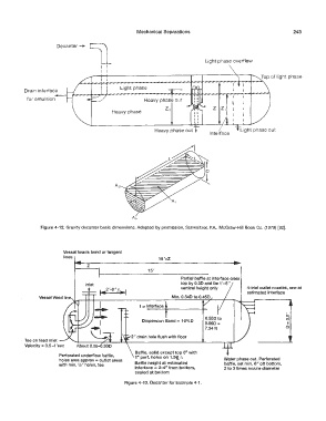
                Figure 4-12.  Gravity decanter basic dimensions.  Adapted  by permission,  Schweitzer,  P.A.,  McGraw-Hill  Book Co.  (1979)  [32].


                         Vessel heads bend or tangent
                         lines
                                                             15'+2
                                  z
                                                         15'
                                                                     Partial  baffle at interface clear
                                 Inlet                               top by 0.3D and be 1'-6"
                                  t   ,.r·O"in/llnj                  vertical  height only    4-trial outlet nozzles,  one at
                                                                                              estimated interface
                                                                 Min. 0.340 to 0.450
                                                      I=' Interface

                                                                                                            0
                                                                              0.550 to                      (")
                                                      Dispersion Band= 10%0
                                                                              0.660 =                       c
                                                                                                             II
                                                                              7.34 ft
                                                  2" drain hole flush with floor
          Tee on feed inlet
          Velocity= 0.5-1'sec
                                                    Baffle, solid except top 6  .. with
                       Perforated underflow baffle,   1 .. pert.  holes on  1.5<t_  11
                       holes area approx = outlet areas                              Water phase out.  Perforated
                       with min. W' holes, tee      Baffle height at estimated       baffle, set min. 6"  off bottom,
                                                    Interface = 2-4  .. from bottom,   2 to 3 times nozzle diameter
                                                    sealed at bottom
                                                Figure 4-13.  Decanter for Example 4-1.
   268   269   270   271   272   273   274   275   276   277   278