
Page 285 - APPLIED PROCESS DESIGN FOR CHEMICAL AND PETROCHEMICAL PLANTS, Volume 1, 3rd Edition
P. 285
Mechanical Separations 255
clean gas
r,,
- - .,
part.cte-laoen gas
Materials of construction
Packing of York-Fiberbed high efficiency mist eliminators consists of
ceramic, glass, polypropylene, fluoropolymer fibers. Cages and
frames are fabricated from all stainless steels and other weldable Collection
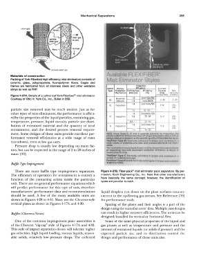
alloys as well as FRP. KOCH Primary Efficiency Element
type Collection Particle SJZe Efficiency µre�re Bad
Mechanism (Microns) (%) Drop Velocity
Figure 4-27A. Details of a cylindrical York-Fiberbed® mist eliminator. (lnche.WG) (f't/Mln)
Courtesy of Otto H. York Co., Inc., Bullet in 558. BD Brownian :>3 Es,enttally 100 2-20 5-40
Up 1099.95
<3
Diffusion
>3 Essen holly 100
IC Impaction 7--9 250-
450
particle size removed may be much smaller. Just as for 1-3 05-99 1-
other types of mist eliminators, the performance is affect- >J Essontial ly 100
ed by the properties of the liquid particles, entraining gas, IP impaction 1·3 85--97 5-7 400
500
temperature, pressure, liquid viscosity, particle size distri- 05-1 50-85
bution of entrained material and the quantity of total IS Impaction '>3 EssenllOlly 100 ,_ 2 �00-
entrainment, and the desired process removal require- ,:J 15-30 500
ment. Some designs of these units provide excellent per- NOlE: inoe � lC, IP and IS operate prirnONtv ov lmpoci,on 1
formance removal efficiencies at a wide range of rates dbov&collEK)t,on elf101enc!e$ c!•oi:i off ct Qr.l'i II� below' Obovl 75 ot
collf:lci
deilgnrol19Sond d�nd on t"8specmc grovl"1 ol
liQukl
11 0
c,
Fleklf!be 1ype &D. Normoltf ,:ynl"l(fr\col In
and
(turndown), even at low gas rates. Wide vot1ety of mal'eflal ond ,lzt1� wilt po:::l<ad element 01& Mo:1o J
Pressure drop is usually low depending on many fac- sanes
tors, but can be expected in the range of 2 to 20 inches of AJIIO ovo11oble cs wound bedi [Marie II or 1111 tor lower inlti al cosr encl Mt
of repocldr,g. ond w,111 eQi.ll\lCllent cotlecflcn 91!/c ncv o! '°' or
water [33). lower pre1.1ure d1'oP cvallobl, Jr, o
F\e1111ber4' 1ype IC: NormoQy cyti1'dt1eol In :110p,;, o
vcrfefy or malerlcls and 11ZBs
F,exlflber" 11,-palPQlld IS: ormalfy rei;:fo1'1Q'Jklr In shape OJ'l<:I ovo1!0l)lg
Ba!Jle Type Impingement In vorlou, rneltll1.
There are many baffle type impingement separators. Figure 4-278. Fiber-pack® mist eliminator pack separators. By per-
The efficiency of operation for entrainment is entirely a mission, Koch Engineering Co., Inc. Note that other manufacturers
function of the contacting action inside the particular have basically the same concept; however, the identification of
types are peculiar to each.
unit. There are no general performance equations which
will predict performance for this type of unit; therefore
manufacturers' performance data and recommendations liquid droplets run down on the plate surfaces counter-
should be used. A few of the many available units are current to the up-flowing gas stream. See Reference [59]
shown in Figures 4-28 to 4-31. Many use the Chevron-style for performance study.
vertical plates as shown in Figures 4-17 A and 4-30. Spacing of the plates and their angles is a part of the
design using the manufacturers' data. Multiple pass designs
Baffles (Chevrons/Vanes) can result in higher recovery efficiencies. The units can be
designed/installed for vertical or horizontal flow.
One of the common impingement plate assemblies is Some of the same physical properties of the liquid and
of the Chevron "zig-zag" style of Figures 4-17 A and 4-30. gas phases as well as temperature and pressure and the
This style of impact separation device will tolerate higher amount of entrained liquids ( or solids if present) and the
gas velocities, high liquid loading, viscous liquids, reason- expected particle size and its distribution control the
able solids, relatively low pressure drops. The collected design and performance of these units also.