
Page 284 - APPLIED PROCESS DESIGN FOR CHEMICAL AND PETROCHEMICAL PLANTS, Volume 1, 3rd Edition
P. 284
254 Applied Process Design for Chemical and Petrochemical Plants
.. Wire �tro.in!';:i11nt !�esh S!lecif1cat1on9
Job No.--------
p ... , ... ,, A. A;,pl1Mtion Service
••••
u,.itPriu
e./MNo. _ 1. Source or :;:ntrain'Dent:
DRUII OR TANK SP!CIFICA TIOMS N•. U•lt1 J
.• _ ... _ o- .J 2. Oncratlnf' Conditions: Give (1) Jior-�al (2) lfaxirnum
Su'f'lo:•_p/�!._�o.,,_::- -,..,d ...f.,� .... -..a.;,a-
SIH 30" o. o. ,c 10'-o" ilen• L,;,e T)'P•----------------1 (3) I-'.inia,u,-,,, where possible
Te·.-.perature ---------
Pr0ssure
Vapor Ph,1,se
Flow R:lte --------
*Velocity
Density -------- at operating conditions
!�olecular ;ie1!rht
Co-npos1t1o!l or li'ature of Phase---------
Liquid Entr:,.in�ent Phtlse
DISIGN DATA
Op•rath11 Po, •• ,_ ;5 PSl..f...__ O,•Ntl11e r.... - //0 "P. ',uant1ty (if kno,m): -------------
D•1l1n Prn1we lop PSI L_ 0.1t1,. T--,, -139 "F. Density:
Cod• AJ ME s,... YfJ Letliel c.,11,. �""'�--- o-11ty el C...Mflot1 _..J.L..Lhlcv. tt r � ;f �� ;t;!.n-s � i-o-n- ,---------------
M111u;al11 Sh.II Law �•�«•OCt'i!CC r1t«t/ HM41 t.ew,-�, Jl«•J S...en1 C•r'•"" ,j;•/
Lhllnf; Metel No R11 ....... •rPle,tlc __ = ,.,.•-------------1
B,1c.k IV• Ce91-1_..:;M;,; • ---r-4 Composition or t:ature of Entrainment: ------
h11u11al e.,,.,..,1 ... All•-nce � ,! .,. S.11 s..,.,u,.,_,.y�,.s'---- '"'•lwtl•: Cifr •• D Nt, a .. , -11o•P
NOZZLl!I ......... Droplet Si?.es or distribution (if known):
s.,..1c• N.. R9<11'tl!. Slae ,.,, •• c1 ••• '•cl"' Solids Content (Compoaition Md Quantity): _
....
'"'"' ". I.SO ,a T,/ A Dissolved:
v ..... o .. ,
6-
'lTJ
I.So
Llquitl! Oi.t .e" ,.ro A!TJ "'
0,.1,, iluspended:
s.ter., v.1 .... I .... ,so RTJ " 3. Perfor:1iance
u.'
Ln11I C-nl
�7J
JI•
.... 2 In .... 0 c.c...-t;,. " Allo�a;1e Tot�l Se�arator Pressure Dro�:
,,. .. -r.,
£
I
,
Ge,• c1 ••• :I, ,i" JSO A!TJ ...
"'""""'• .. . .. ,s. A!TJ N Allo..,able ���esh Pressure Drop:
H•oh J,.c,.,c/ ,,Q/o.;-,,,,
Low Lc'll"c/ .&Jl11r- �· IS't> IPTJ r Al10C1able Entrain,nent:
IIIMAHS r1i:oah Thicnless Recolll!Dended:
lAl,·,�NJ�"''- ,',o be .S'/ondlordll'l•d.-• 1.•,1,111·cK·N>-,h.,-,.-../ r� ,.,...,., ·�;,/,1 ,L-.1. B, Construction and Installation
P,o�··d& .:,u--11r'J- o,.,J ,',o-h#fd .. do .,t;,. --•,I. ,.�
•, lc"i,,•4 11 ..... , .... *Di2,,oeter, I.DI
o ... I I I I I
P.O. T•:---------------------------- Construction i:·iaterial:
*Position (Horizontal, Vertical, Inclined):
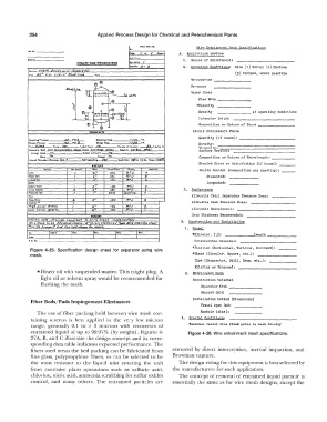
Figure 4-25. Specification design sheet for separator using wire
mesh. *Shape (Circul�r, Square, etc.):
Type (Ev<1.por.�tor, Still, Drum, etc,):
Existing or Proposed:
• Heavy oil with suspended matter. This might plug. A 2. Entrain:nent J.!esh
light oil or solvent spray would be recommended for Construction !�ter1al
flushing the mesh.
Separator Y.esh ------��
&.lpport Grid
Installation ,!ethod (Di!nensions)
Fiber Beds/Pads Impingement Eliminators
Vessel Open End:
The use of fiber packing held between wire mesh con- �'.anhole (size):
taining screens is best applied in the very low micron c. Special Conditions:
range, generally 0.1 to > 3 microns with recoveries of *Assumes vessel size �ixed prior to mesh 1nau1ry
entrained liquid of up to 99.97% (by weight). Figures 4- Figure 4-26. Wire entrainment mesh specifications.
27A, B, and C illustrate the design concept and its corre-
sponding data table indicates expected performance. The
fibers used mean the bed packing can be fabricated from removed by direct interception, inertial impaction, and
fine glass, polypropylene fibers, or can be selected to be Brownian capture.
the most resistant to the liquid mist entering the unit The design rating for this equipment is best selected by
from corrosive plant operations such as sulfuric acid, the manufacturers for each application.
chlorine, nitric acid, ammonia scrubbing for sulfur oxides The concept of removal of entrained liquid particle is
control, and many others. The entrained particles are essentially the same as for wire mesh designs, except the