Page 331 - APPLIED PROCESS DESIGN FOR CHEMICAL AND PETROCHEMICAL PLANTS, Volume 1, 3rd Edition
P. 331

Mixing ot Liquids                                       299

                       T                          ......  /   420   Viscous flow,  NRe  less  than  10 to 300 is expressed:
                                             @....-
                                     60       -;;,"
                 \              20        .,.,  /                      K
                10                    /                            p  =  _ 2  µ(N.)2  (D)3                    (5-4)
                                        /
                   \             ......                                g
                    \      ,,.,   ......
                      \              50                         K 2  = from Table 5-1
               100     ,�       15                               P  =  power,  not power number,  P 0
                         /
               200
               300
                           \  \+                                Fully developed turbulent flow,  NRe  over 10,000, in a tank
                              r�o    40                         10%  of the tank diameter:
               400                                              containing  four equally  spaced  baffles  having  a  width  of

              ,.,ooi                                               p  =  _ 3  p  (N  )3  (D )5                (5-5)
                                                                       K
                                                                        g     s
                  l                                               K3  = from Table 5-1
                  t                  30
                             ..
             2,000!         ""  ...   5                 1150    where  g  =  conversion factor,  32.2 lb mass-ft/lb force/
                             ..
                                                                          (sec)  (sec)
                                                    e
            j.,oo           .                       a:  -             H  =  total  potential  head during flow,  ft
                             c
                                                    c.
                            ..
                                                    ..
                                                    ...
                                                                       P  =  power,  ft-lb/sec
                                                    •  ...
                      ..    �    '#,  l             <I)               W  = impeller blade width, ft
                                                                      µ  = viscosity,  lb/ft-sec
            j,.oo,f   ;:.                           •  ...             p  = density,  pounds/  cu ft
                                                    �
                      c
                                                    .!!
                      i
                                                    e
                      �     ilJ 20                  0..   1750        N,  = revolutions/sec
                            o,
                 Example:                                         Horsepower,  (HP)  =  P  /550               (5-6)
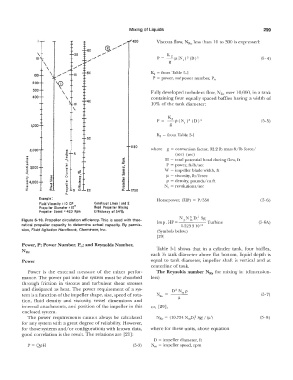
                 Fiuld  Viscosity  : IC  C P   Construct Lines  I  and  2
                 Propeller Diameter =  10"   Reod  Propeller  Mixing
                 Propeller Speed  : 420  Rpm   Efficiency  of 54 %
                                                                            NN 3 D5Sg·
          Figure 5-10.  Propeller circulation  efficiency.  This is used with theo-   1   HP   p   m   I   T  b'   (5-6A)
          retical  propeller capacity to  determine  actual  capacity.  By permis-   mp.   =  1.523 31013   ur  me
          sion, Fluid Agitation Handbook,  Chemineer,  Inc.        (Symbols below)
                                                                   [29]
          Power,  P;  Power Number,  P 0;   and Reynolds Number,
          NR,,                                                    Table  5-1  shows  that in  a  cylinder  tank,  four baffles,
                                                                each  ).{2  tank diameter above flat bottom,  liquid depth  is
          Power                                                 equal  to  tank  diameter,  impeller  shaft  is  vertical  and  at
                                                                centerline of tank.
             Power  is  the  external  measure  of the  mixer  perfor-   The Reynolds number NRe  for mixing is:  (dimension-
          mance.  The  power put into the system  must be absorbed   less)
          through  friction  in  viscous  and  turbulent shear  stresses
          and  dissipated  as  heat.  The  power requirement of a  sys-
          tem is a function of the impeller shape, size, speed of rota-                                       (5-7)
          tion,  fluid  density  and  viscosity,  vessel  dimensions  and
          internal  attachments,  and position  of the impeller in this   or,  [29],
          enclosed system.
             The  power  requirements  cannot always  be  calculated   NRc  =  (10.754·  NmD;2  Sg)/(µ')      (5- 8)
          for any system with a great degree  of reliability.  However,
          for those systems and/or configurations with known data,   where for these units, above equation
          good correlation is the result.  The relations are  [21]:
                                                                 D  =  impeller diameter,  ft
             P  =  QpH                                   (5-3)   Nm  =  impeller speed,  rpm
   326   327   328   329   330   331   332   333   334   335   336