
Page 335 - APPLIED PROCESS DESIGN FOR CHEMICAL AND PETROCHEMICAL PLANTS, Volume 1, 3rd Edition
P. 335
Mixing of Liquids 303
11111 I I I I I I T
10� Curve No. I O 20" Propeller 21" Pitch in 54" Tonk T/D = 2.7
•• = 3.o
u r a"
"
"
.. 2 CD
6..
..
6..
u
II 3 e 411 II 4 n II II 1311 II II : 3.3
II 4 6) 12" II 11.8" M U 54" " U :4.5
II 11 II u 11 11 u U II
5 0 4 8 13
� fl N 6 • ·411 II 811 II II '' '' : 3,3
-. 13 Baffles 0.1 T l--+---f-4-+-++-1-1-l
,..._ ..-�.---,-..,.......,-,--,-..,..,.,.�---,�.--,......,.....,...,....,�������__J
1
�
2i---t--t--t-t-ir-+t-tt---j � iib,;j-l-i-tti-t------t---lf-4-+++f+1f---+--1--l-+-J'-+l-1+-__j--J-.J.-.jf-l...W-1+ --l---+--+-.l+.U.
I �-..�J. I
f-tt����ii!lf§-�·gif�i·���t�imt-�i��itt11S
�...
_,l" " '�"'---.... - I I
- Propellers ,No Boffles
I.O :: Volues of i P
=
0.5 � Belc,w NRe of 300, j � :Np (a-log NRe) ���lHm�-�j:ee!i��iiiiWi�����il
5
,_
r» D \
- Above Nae of 300, i ,
- (-.!L {_2._\ ---r- - 4:
0.2 - pN3oo/\N2o/
With Boffles, For All NRe f: Np I
0.1-.LLLIIIIII I I I 111111
2 5 2 5 2 5 2 5 2 5 2 5
10
Reynolds Number
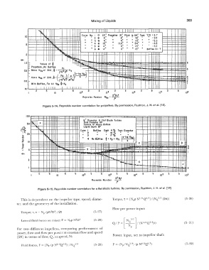
Figure 5-14. Reynolds number correlation for propellers. By permission, Rushton, J. H. et ai. [18].
,oo��������������������������:=��:!:!:������tlt!l�����±±liH
I;;
6" Diameter 6 Flot Blade Turbine
"'-
50 � A Tonk Diameter 18"
� Turbine 6" Above Bottom
Liquid Depth 18"
tj., "I.., Curve I 2 Baffles Each 4 % Tonk Diameter
�
a,
10 °lo
�
� -- 20 1---+-11.,io:+ � +-H-1H+--l--+-+-l-+I 11 II 3 II ,, U u 17 Ofo II 11 II 11
� !llii • 4 No Balllta f : Np.;. Nfr r-lo: NR,)
10 5 ; C
f������ff�l���-���-�,-!,�i�-�B���������������������D��
:
2 5 2 5 2 5
D 2 Np
Reynolds Number
f
Figure 5-15. Reynolds number correlation for a flat blade turbine. By permission, Rushton, J. IL et al. [i 8].
This is dependent on the impeller type, speed, diame- (5-30)
ter, and the geometry of the installation.
Flow per power input:
Torquet rv t > NP (pN2D5)/21t (5-27)
Lateral fluid forces on mixer; F = NrP N 0- 1 (5-28) [ N 5/3 l
2
QI p = � r I (N1;3Q213p) (5- 31)
For two different impellers, comparing performance of
power, flow and flow per power at constant flow and speed
[29] in terms of flow, Q, at speed, N: Power, input, net to impeller shaft:
(5-29) (5-32)