
Page 334 - APPLIED PROCESS DESIGN FOR CHEMICAL AND PETROCHEMICAL PLANTS, Volume 1, 3rd Edition
P. 334
302 Applied Process Design for Chemical and Petrochemical Plants
where <I> is read from the charts and the constants a and ever, in the extremities of a vessel, the motion would be
b are given in Figure 5-16. laminar. In this case, as in all others, the tank baffling is a
Figure 5-17 is useful for determination of horsepower major factor for performance of the system and the power
during turbulent flow for various types of impellers, and and flow results.
Figure 5-18 is useful for laminar flow. Also see Figure 5-19. For NRc > 1000, the properly baffled tank is turbulent
Flow and power numbers each decrease as the throughout. NQ and P O are independent of NRe· If the
Reynolds number increases. In unbaffled tanks, a vortex tank is not baffled, a "forced vortex" dominates the flow
forms that takes over the flow regime and does not allow in the vessel.
the usual relationship to describe the performance of the For NRe > 1000, in fully baffled tank is turbulent.
mixing operation. It is proper and good practice to pro-
vide baffles in all vessels (see later description for the NP= P/(N3 Df)(p) (5-25)
physical configurations).
At high NRe, the power number, P 0, stays reasonably Pumping effectiveness or pumping per power is impor-
constant, thus, viscosity has little effect on the power tant for flow controlled processes [29).
requirements. When moving to lower NRe through the The shape, size, and baffling of a specific mixing vessel
laminar region into the viscous region, the viscosity efTect significantly influences the Reynolds number, flow, and
power numbers.
increases. In the laminar range [29)
Di= 394 (HP/n Sg NJ,)1/5 (5-25A)
(5-23)
Other relationships [29) for one Lype of impeller (not
or, P p µ (5-24) different types)
0
for all other parameters constant.
For 50 < NRe < 1000 [29) is the transition range. In the Q -- ( 1 ) , ratio of flow to power (5- 26)
NQ
2
immediate impeller area, the flow is fully turbulent; how- p po p N 02
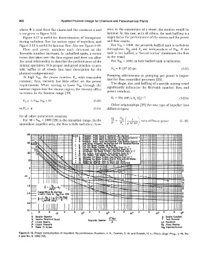
- CurYt I Proptlltr. re" Equal to lamtltr , FOllr Its Each 0.1 T
100
�ual to � alltltr I No B3!fl"
J2
•
Propeller , itcb
•
�
4 P � tr , P � tcb Twiet lht Dlamtltr {off tffl11 E,th 0.1 T
111 ' . i Proj>t!ltr , itch Twiet the Diamtltr, No Baffltt
50 '5,&;i;e '- . � lta, ra3 rop/iller, No B � lts bu O - 1ftrtd sllion
.
fflts
lot Si'l • lode urblrit , No
91 ,'\.. ' . i Flot Sia-Bladt Turbint, Fo � r 8afflts Eafh 0.1 T
3,4 -" -, ' 7 Curved Sia-Bladt Turbirie, Hr Bcifflll och 0.1 T
8 Arrowlltod Sla-Blodt Tur Int, Four Bafflu Eoch 0.1 T
20 _1,2 • 9 Fein Turbine, Elght·Blad � our Bcifflts Ecich Of T
10 ..... �;, • 10 Flat Poddlt, Twci-Bladt ur Baffles Each 0.1
� � � � 14 " II � hroudtd Sia-Blade Turblne,FourBofflH Each 0.1 T
�
10 - - • 12 hroudtd Six-Blade Turbine,Stotor Rin9r.w1tb 20 Blodts
13 Paddle,=: l:fflts , Doto of Miiier and ann
"
off In Dcita of White and Sumerfonl
• 14 Paddlt
..... �- I I '::6 - 6
..... �
" -
""'
... �'""" ......... r-s, � r--::,.. ......_ 14" r-s, 7 ._8 ...... __ - 7
8
-
.....
"'-
13
9
2 ' r-, � t-- ..._ -11,12- ·- � i!,O ..... --14 9
10
--- f= pt 3 -13 4
y
1.0 5=Np ""'� ' 14 4 --- -- 12
--- Eactl!I When No Baff111
0.5 ,___ in fN 2 3
- wblch Call for HRf OYtr 300
= t: (� (�l ci·log NRe) -..-.� 2
0.2 ,'ND N' b
·-1 I 1111111 I I
0.1
I 2 5 10 2 2 5 10 1 2 5 2 2 5 io•
D l111p1ller Dia11eter 9 GravltJ Conatont
N lraptlltr Rcitatloncil Speed R17nold1 Nu111b1r T Tonk Dlcimtter
f Liquid Dtnti!J o,b Cautcinta
f Liquid Vlacoslty Np Power Number
P Power fl. lb./Mc. NR, Rt,nolds Number
Figure 5-13. Power consumption of impellers. By permission, Rushton, J. H., Costich, E. w. and Everett, H. L., Chem. Engr. Prog., v. 46, No.
8 and No. 9, 1950 [18].