
Page 336 - APPLIED PROCESS DESIGN FOR CHEMICAL AND PETROCHEMICAL PLANTS, Volume 1, 3rd Edition
P. 336
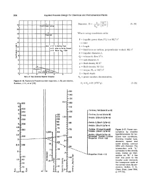
304                       Applied  Process Design for Chemical  and  Petrochemical  Plants

                                                                                      (Ql/3J
                                                                                  1
                                                                    .
                                                                                   l/3
                                                                                       N 113
                i                 (Flot  6  Blade  Turbine)                     N  Q
               4                        b                          Diameter,  D  =  ---  --                    (5 - 33)
               2  0  '                 I   I
                                         b                        Where using consistent units:
                B
                                       !Proptllerl
                6
                                                                    P =  impeller power draw,  FL/tor ML2/t 3
              ...  I  4                                             t =  time
              �·  2                        n=O  when  no  Vort11  Pruenl   F = fluid force on turbine,  perpendicular to shaft,  ML/t 2
              ....                     Not,: n  = O  for Baflltd  Tank   L =  length
              &,
              ..
              .
              a
                                           n=O  Below  NRe  = 300
                8  .
              �   0                                                D  =  impeller diameter,  L
              0                                                    Q = volumetric flow,  L 3 /t
              u
                6                                                  T =  tank diameter,  L
                                                                    p =  fluid density,  M/L3
                4
                               .is,                                 µ=fluid viscosity,  M/(Lt)
                2            (Propeller)  -   __
                                I    - �--�   r---......            't =  torque, FL, or ML2/t2
                0                (Flot 6  Blocle  Turbine)          Z  =  liquid depth
                 0              2             4
                     Ratio  of  Tank  Diameter/Impeller  Diameter   NP  =  power number,  dimensionless,
             Figure 5-16.  Factors in Froude number exponent,  n.  By permission,
             Rushton, J. H., et al.  [18].                                                                     (5-25)
                                                           150
                                                           140
                                                           130
                                                           120

                                                           110
                    500                                                     Turbine, Flat Blade(6 or 8)
                    450                                    100
                    400                          120                        Turbine, Curved  Blade (6)
                                                 110   1.5   90             Paddle  3/Shaft ( D/W:  6)
                    350                          100
                                                           80               Paddle  2/Shaft (D/W=6)
                    300                          80                         Paddle  I/Shaft (D/W =4
                                                 70
                4   250                                    70               Turbine  Pitched  Blade(6)   Figure  5-17.  Power con-
                                                                            Poddlt I/Shaft (D/W=6)
                                        1,000    60                                               sumption  by  impeller
                                                                            Paddle  1/Shaft(D/W:  8)   type/dimensions  for  tur-
                    200                                    60               Shrouded  Turbine + Stator   bulent  flow  conditions.
                   --------------                                           Propeller  Pitch =  20   Knowing  impeller  type,
                3                                     .9                                          diameter,   speed  and
                                          10                                                      batch  density;  connect
                    150                                   ... �o                                  RPM  with  diameter.  The
                                        ..       30         .........  .....  ......              intersection  with  "A,"
                2                       ..                    -  ..   ... ....                    connected to the density
                                                              ..
                                                                                                  scale,  makes  an  inter-
                                        :II
                                        0
                                        a.
                    100                 ..   .I                            Propeller Pitch =  ID   section  on  "B."  A  line
                                        :!           ,..,.   40":                                 from  this  point  to  the
                                                     ..
                                                              ::,
               1.5   90                 0        20   ..     ....,.                               impeller  scale  intersects
                                                              u
                                        :c .01       �.6      ...
                    80                               C)      ....                                 the  horsepower scale  at
                                                                                                  the correct value. By per-
             ..     70                            15  -�                                          mission,  Quillen,  C.  S.,
                       a.
             Q.        E                             ts                                           Chem.  Engr.,  June 1954,
             a::  1.0   a::         ct   Ill   0   12   en                                        p.  177 [15].