Page 333 - APPLIED PROCESS DESIGN FOR CHEMICAL AND PETROCHEMICAL PLANTS, Volume 1, 3rd Edition
P. 333

Mixing of Liquids                                       301

                                Table 5-1
                         Baffled Cylindrical Tanks
                                            x,         Ks
                                          Viscous   Turbulent
           Propeller,  3.blade,  pitch = diameter  ....   41.0   0.32
           Propeller,  3-blade,  pitch = 2  diameters ..   43.5   1.00
           Turbine,  flat  blade,  4  blades   .   70.0   4.50
           Turbine,  flat  blade,  6  blades   .   71.0   6.30                                         0=4"
           Turbine,  flat  blade,  8  blades   .   72.0   7.80
           Fan  turbine,  blades  at  45\ 6  blades   .   70.0   1.65
           Shrouded  turbine,  stator  ring   .   172.5   1.12         0.025
                      -
           Fl � )w1dle 4  2  � I ���   _( ���� l � - ��� -e}'.   .   43.0   2.25   0.02
           Flat  paddles,  2  blades,  D/W = 6   .   36.5   1.60
           Flat  paddles,  2  blades,  D/W = 8   .   33.0   1.15
           Flat  paddles,  4  blades,  D/W = 6   .   49.0   2.75       0.015
           Flat  paddles,  6  blades,  D/W = 6   .   71.0   3.82

           *By  permission,  R.  H.  Rushton  and  J.  Y.  Oldshue,  Chem.  Eng.   0.010               '.J=3"
            Prag.  49,  161  (1953)
                                                                   p

             Oldshue  [29]  points  out that to  identify  the turbulent
           range  as  beginning  at a  specific  NRe  may  not be  exactly
           correct,  as  it  actually  varies  with  different  impeller   0.004
                                                3
           designs.  This range may vary from N  Re= 10 to N  Re = 10 5,
           so  for common  use  1\'Re  =  10 is  taken  as  the  turbulent   0.003                   P VS.  N
                                     5
           range for all impellers.                                                                  0/T=l/3
                                                                                                     C/0=1.0
           Power Relationship                                                                          �=1.0
                                                                                                       U=l .O
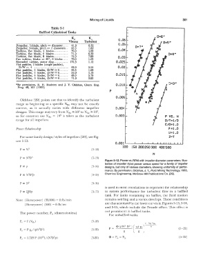
             For same family design/styles of impellers [29], see Fig-                                 i!=T
           ure 5-12:
                                                                       0.001'--�...__,_�L.-L.-.L....L....L..JL...LI-L...L.LI
                                                                           100  1 so 200  250  300 400  500
             P  ex  N 3                                 (5-12)
                                                                                             N
                                                        (5-13)
                                                                Figure 5-12. Power vs.  RPM with impeller diameter parameters.  Illus-
                                                                tration  of impeller input power versus speed for a  family of impeller
             p  (X  p                                   (5-14)   designs,  but only of various diameters,  showing unifonnity of perfor-
                                                                mance. By permission, Oldshue, J. Y., Fluid Mixing Technology,  1983,
                                                        (5-15)   Chemical  Engineering,  McGraw-Hill Publications Co.  [29].
             p  (X  05                                  (5-16)
                                                                is  used in  most correlations to  represent the relationship
             P  cx:QHp                                  (5-17)   to  system  performance  for  turbulent flow  in  a  baffled
                                                                tank.  For  tanks  containing  no  baffles,  the  fluid  motion
           Note:  (Horsepower)  (33,000)  = ft lb/min           remains swirling and a vortex develops.  These conditions
                (Horsepower)  (550)  =  ft lb/sec               are characterized by the lower curves in Figures 5-13, 3-14,
                                                                and 5-15,  which include  the Froude  effect.  This  effect is
                                                                not prominent in baffled tanks.
             The power number,  P (dimensionless)
                                O
                                                                   For unbaffled tanks:
                                                        (5-18)
                                                                                         a-log  NRc
                                                                   p  =  <l>  (pNJ  05  )   (  N2  D)   h
                                                        (5-19)                                               (5- 21)
                                                                            g       g
                                                        (5-20)                                               (5-22)
   328   329   330   331   332   333   334   335   336   337   338