
Page 392 - APPLIED PROCESS DESIGN FOR CHEMICAL AND PETROCHEMICAL PLANTS, Volume 1, 3rd Edition
P. 392
360 Applied Process Design for Chemical and Petrochemical Plants
steam OperatinQ _.,..,.. V" lent. Figures 6-17 and 6-18 are used to handle the evalua-
_ Pressure lb. GaQe tion on an equivalent air basis. If actual performance
6 v ....
I\ � .....- curves are available for the temperature and vapor mix-
.,,,.
I � _v ture in question, conversion to an equivalent basis is not
necessary except for test purposes.
.. 5 / � /
......
"" / .....- Example 6-2: 70°F Air Equivalent for Air-Water Vapor
"
(!) I � -.,,,.,.-
�4 Mixture
/ ., � /'
I.,. � .,,,.,.- ,.,,.--- What is the 70°F air equivalent for 500 pounds per
- / / - hour of a mixture containing 150 pounds per hour of air
/
and 350 pounds per hour of water vapor if it is at 350°F.
"'
e
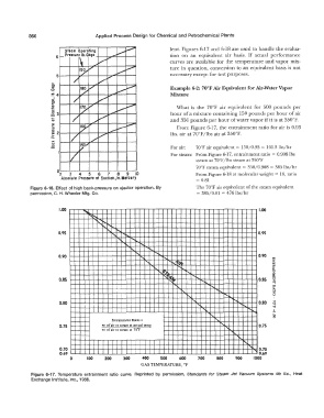
... � , � ,.,....... From Figure 6-17, the entrainment ratio for air is 0.93
:::,
:: 2 lbs. air at 70°F /lbs air at 350°F.
/
0:. 1/ /
...
u 150""
"
ID v For air: 70°F air equivalent= 150/0.93 = 161.3 lbs/hr
v For steam: From Figure 6-17, entrainment ratio= 0.908 lbs
I
steam at 70°F /lbs steam at 350°F
70°F steam equivalent = 350/0.908 = 385 lbs/hr
02 3 4 5 6 7 8 9 10 From Figure 6-18 at molecular weight= 18, ratio
Absolute Pressure at Suction, In. Mercury = 0.81
Figure 6-16. Effect of high back-pressure on ejector operation. By The 70°F air equivalent of the steam equivalent
permission, C. H. Wheeler Mfg. Co. = 385/0.81 = 476 lbs/hr
1.00 1.00
' ........
............
.... ""
0.95 ....... ........ ........ 0.95
' ....... ..
.......
.........
..... '
' .......
0.90 ' -, "'""'-" '!J 0.90 rr,
'
�
�
i
"- 'l)'j ;-.. r-, �
N� ........... rr,
...,
0.85 0.85 z
' 'I' ""
"i... ... i-,.. ;
.... ..........
! ' ........... i5
...,
0.80 I"'- ' ...... ...... ...._ 0.80 q
I " ........ 'Tl
.!!..
,...._ 8
Entrainment Ratio= '-
......
0.75 wt of air or steam at actual teme ' 0.75
wt of air or steam at 70'F
....
.....
r-,...
0.70 '
... 0.70
0.69 0.69
0 100 200 300 500 600 700 800 900 1000
GAS TEMPERATURE, °F
Figure 6-17. Temperature entrainment ratio curve. Reprinted by permission, Standards for Steam Jet Vacuum Systems 4th Ed., Heat
Exchange Institute, Inc., 1988.