
Page 389 - APPLIED PROCESS DESIGN FOR CHEMICAL AND PETROCHEMICAL PLANTS, Volume 1, 3rd Edition
P. 389
400
300
200
:----+-·
100
90
80
70
60
50
40
30
20
10
9
... 8
::, 7
0 6
"'
.J:> 5
<t
a, 4
�
E 3
E
- 2
...
::,
-
"'
"' ...
0..
c:
0 1.0
- .9
'-'
:::,
(/) .8
.7
.6
.5
.4
.3
.2
.01 L....J..��-'-..;,_;c.....J.....l-.1..-1--'-..J.......1-J....-'-'--L.�'-'--'--'--'-'-""---'--'-�'-'--'-.1..-...1.-'-...L.....J--l...--"-'----'--'--'---'-...L.....J-'---"-�--'--'--'--'-..J.......1--l......._,
0 i2 24 36 48 60 72 84 96 108 120
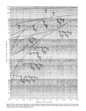
Capacity - lbs. Air per hour
Figure 6-118. A typical relative comparison of various designs of steam jet ejectors. Based on same steam consumption, 100 psig steam
pressure and 85°F water. Curves represent the capacity of ejectors designed for maximum air handling capacity at any one particular suction
pressure. By permission, Graham Manufacturing Co.