Page 390 - APPLIED PROCESS DESIGN FOR CHEMICAL AND PETROCHEMICAL PLANTS, Volume 1, 3rd Edition
P. 390

358                       Applied Process Design for Chemical  and Petrochemical  Plants
                                                                                110        .......... ....---..----,
                                                                            ·-!�   ......--....--5
                                                                            0 c»l08t---..+---->4---+---I
                                                                             ....
                                                                             �  106 r---+-----------t
               80   Rotary piston                                            "'
                   oil-sealed                                                �  104t---+---+----+----1
                                                                             o,
                                                                             E
             ...                                                             �  102  R  .  .   Sf   p
                                                                                    a1smg  eom  r
             ::E
             o   60                                                            100
             <(
             ..
             af                                                              �  9ar=::==:t:::==:t:::::z::��-l
                                                                                         Unstable<
                                                                             >
             St                                                              o  96  2--+----r--+-t-T
             c
             't                                                              ! 94  Dropping Steam Press.
             "'  40
             ...
             :,
                                                                             ·[  92             Break
                                                                             Q)
               20                                                            Cl  9094   96   98    100   102
                                                                                      Design  Capacity  1 %
                                Basis:  70"F sealing water
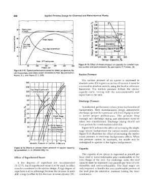
                                                                   Figure 6-13. Effect of steam  pressure on capacity tor constant sys-
                               100    150     200    250     300
                                    PressJre,  torr               tem suction and back-pressure.  By permission,  P.  Freneau,  [4].
             Figure 6-11C. Typical performance curves for steam jet ejectors, liq-
             uid  ring pumps,  and rotary piston oil-sealed pumps.  By permission,   Suction Pressure
             Ryans,  J.  L.  and Roper,  D.  L.  [24].
                                                                     The  suction  pressure  of  an  ejector  is  expressed  in
                                                                   absolute units.  If  it is given as inches of  vacuum it must be
                                                                   converted to absolute units by using the local or reference
                                                                   barometer.  The  suction  pressure  follows  the  ejector
                                                                   capacity  curve,  varying  with  the  non-condensable  and
                                                                   vapor load lo  the unit.
                                                                   Discharge Pressure

                     -;fl.                                           As indicated, performance of  an ejector is a function of
                      �1401----+---4<�<\-----,l-#-,,-+  ......  -+--+---I   backpressure.  Most  manufacturers  design  atmospheric
                     i120--t--iM---t----lir#-lr-+---Mi:--+---1     discharge ejectors for a pressure of  0.5 to 1.0 psig in order
                     Cl                                            to  insure  proper  performance.  The  pressure  drop
                     (.)
                     ..
                     c  100--+�-+-�t-1--N-r--+-
                      "'
                     ·;;;                                          through  any  discharge  piping  and  aftercooler  must  be
                     a  aO--tt--t---f-.,....,r---r--t--+---1       taken  into  consideration.  Discharge  piping  should  not
                                                                   have pockets  for condensation collection.
                                         A= 150  lb.  Pressure
                        60 ----+--+-tt--+-i   (Design  Basis)        Figure 6-15 indicates the effect of  increasing the single-
                                         B =200  lb.Pressure
                        40 1--+-+--+-+-1t-,f--lC =250 lb. Pressure   stage  ejector backpressure  for various  suction  pressures.
                                                                   Figure  6-16 illustrates  the effect of increasing  the motive
                                                                   steam  pressure  to  overcome  backpressure  effects.  When
                                                                   this  pressure  cannot  be  increased,  the  nozzle  may  be
                         O    I      34  5      67  8              redesigned to operate at the higher backpressure.
                          Absolute  Pressure  at  Suction, In. MercurJ
             Figure  6·12.  Effects of excess steam  pressure  on ejector capacity.   Capacity
             By permission, C.  H. Wheeler Mfg.  Co.
                                                                     The  capacity of an  ejector is  expressed  as  pounds per
             Effect of Superheated Steam                           hour total  of non-condensable  plus  condensables  to  the
                                                                   inlet  flange  of  the  unit.  For  multistage  units,  the  total
               A  few  degrees  of  superheat  are  recommended    capacity must be separated into  pounds  per hour of con-
             (5-15°F), but if superheated steam is to be used, its effect   densables  and  non-condensables.  The  final  stages  are
             must be considered in the ejector design. A high degree of   only required  to  handle  the non-condensable  portion  of
             superheat is of no advantage because the increase in avail-   the  load  plus  the  saturation  moisture  leaving  the  inter-
             able energy is offset by the decrease in steam density [ 16].   condensers.
   385   386   387   388   389   390   391   392   393   394   395