
Page 40 - APPLIED PROCESS DESIGN FOR CHEMICAL AND PETROCHEMICAL PLANTS, Volume 1, 3rd Edition
P. 40
Process Planning, Scheduling and Flowsheet Design 25
C-2 Single compressor in different service (by incineration, vent, and cooling tower waters and number
fluid or compression ratio) from C.-1 's above. all like process items within that system, for example:
S-1 First separator in a process Reactor System, R: Reactor is RD-1
S-2 Second separator in a process Reactor vent cooler is RE-1
S-3a Two identical separators connected in Reactor vent condenser is RE-2
S-3b parallel, in same process service. Reactor recycle pump is RP-1
Level control valve is RLC-1
Relief valve is RSV- l
Some equipment code systems number all items on Then, establish the same concept for all other unit or
first process flowsheet with 100 series, as C-101, C-102, P- block processing systems. This is often helpful for large
l 06 to represent ccmpressors number 101 and 102 in dif- projects, such as refinery or grass roots chemical processes.
ferent services and pump 106 as the sixth pump on the Valve identification codes are usually used in prefer-
sheet. The second sheet uses the 200 series, etc. This has ence to placing each valve specification on the flowsheet.
some engineering convenience but is not always clear This latter method is feasible for small systems, and is most
from the process view. workable when a given manufacturer (not necessarily the
same manufacturer for all valves) can be selected and his
To keep process continuity clear, it is usually best to
number all like items sequentially throughout the process, valve catalog figure number used on the flowsheet, For
with no concern for which flowsheet they appear on. Also, large jobs, or where many projects arc in progress at one
another popular numbering arrangement is to identify a time, it is common practice to establish valve specifications
system such as reaction, drying, separation, purification, for the various process and utility services (see Figures 1-25
and 1-26) by manufacturers' catalog figure numbers.
These are coded as V-11, V-12, V-13, etc., and such code
numbers are used on the flowsheets wherever these valves
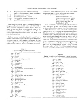
Table 1-2
A System of Equipment Designations
AD -- Air Drier
AF - Air Filter Table 1-3
Ag - Agitator Typical Identification for Flowsheet Process Functions
B- Blower
BR - Barometric Refrigeration Unit AS-Air Supply
C - Compressor BD-Blowdown
CP - Car Puller
CT -- Cooling Tower BF-Blind Flange
CV - Conveyor CED-Continuous Blowdown
D - Drum or tank CD-Closed Drain
DS - Desuperheater CH-0-Chain Operated
E - Heat Exchanger, condenser, reboiler, etc. CSO- Car Seal Open
Ej - Jet Ejector CSC-Car Seal Closed
Ex - Expansion Joint DC-Drain Connection
F-Fan EBD-Emerg. Blowdown Valve
FA - Flame Arrestor ESD-Emerg. Shutdown
Fi - Filter ( line type, tank, centrifugal)
GT- Gas Turbine FC-- Fail Closed
MB - Motor for Blower FO- Fail Open
MC - Motor for Compressor HC-Hose Connection
MF - Motor for Fan IBD- Intermittent Blowdown
MP -- Motor for Pump LO- Lock Open
P-- Pump ML-Manual Loading
PH - Process Heater or Furnace NC-Normally Closed
R- Reactor NO-Normally Open
S - Separator OD-Open Drain
St - Strainer
ST - Steam Tu: bine P- Personnel Protection
Str -- Stearn trap QO-Quick Opening
SV --- Salety Valve SC-Sample Protection
Tr-Trap SO-Steam Out
V- Valve TSO-Tight Shut Off
VRV - Vacuum Relief Valve VB-Vacuum Breaker