
Page 428 - APPLIED PROCESS DESIGN FOR CHEMICAL AND PETROCHEMICAL PLANTS, Volume 1, 3rd Edition
P. 428
394 Applied Process Design for Chemical and Petrochemical Plants
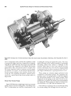
Figure 6-47. Cut-away view of internal assembly of rotary lobe vacuum pump. By permission, Tuthill Corp., M.D. Pneumatics Div., Bull. A-
5/888.
seal or compressant water, and that the capability to hold in sealing the moving vane against the casing. The rotary
a vacuum with higher seal water temperature is reduced. shaft is off-center in the casing to provide a continuously
Typically, for a 95°F seal water, the vacuum may only be 26 decreasing volume from suction to discharge of the
to 27 inches Hg compared to the 28-inch Hg vacuum machine. Other styles of rotary vane units do not have
gauge shown. Also, care must be used to recognize that suction or discharge valves. Note that the volume pumped
the curves represent inches of mercury, vacuum gauge, is expressed as free air, which is measured at 60°F and 14.7
not absolute. To convert, use the 30-inch Hg barometer psia. Figure 6-40 illustrates a typical performance curve.
less the vacuum reading to attain absolute vacuum, inch-
es Hg abs. The estimated pump-down capacity perfor- These pumps are relatively simple mechanical units
mance for a typical liquid-ring vacuum pump is given in compared to rotary-piston pumps. The "pumping com-
Figure 6-38. partment vanes" are spring loaded to hold them against
the off-centered position in the casing/housing. Some
designs do not use springs on the vanes, but rely on cen-
Rotary Vane Vacuum Pumps trifugal force to position the sliding vanes sealing against
the casing wall. These pumps are used for medium vacu-
um ofless than I torr [20]. Also see Parkinson [34].
Figure 6-39 illustrates a single-stage rotary vane vacuum
pump, without external cooling jacket. The sliding vanes Units without an oil pump rely on once-through oiling
(No. 7 in illustration) are oiled by a closed system to aid for vacuum sealing. The oil usage is low for most units.