
Page 431 - APPLIED PROCESS DESIGN FOR CHEMICAL AND PETROCHEMICAL PLANTS, Volume 1, 3rd Edition
P. 431
Ejectors and Mechanical Vacuum Systems 397
hL = Liquid height, ft
K = Non-condensable load factor
L = Latent heat of vaporization of steam, BTU/lb
M = Average mol weight of system vapors
M, = Molecular weight of non-condensable gas
M, = Molecular weight of conclensable vapor
P = Total absolute pressure, lbs/sq in. absolute (or
other consistent units), or system operating pres-
sure, torr
Pa= Partial pressure of air in mixture, lbs/sq in. abs
Pc = Absolute intake pressure of pump
Pct = Piston displacement, cu ft/min
P n = Partial pressure of non-conclensable gas; pounds
per square inch absolute (or other absolute units)
P, = Static pressure, atm
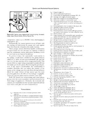
Figure 6-50. Typical rotary displacement vacuum pump, oil sealed, P,, = Vapor pressure of condensable vapor, pounds per
single-stage. By permission, Kinney Vacuum Co.
square inch absolute (or other absolute units)
P' = Partial pressure of a vapor in a mixture, psia
compression. ratios up to 100,000:1 when discharging to P,' = Design suction pressure of ejector, torr
atmosphere [22]. P n" = Final pressure in vessel or system, torr
Mechanically, the pump operates in an oil bath, with P 0" = Starting pressure in vessel or system, torr
the seaiing oil lubricating the pump and seals against P = Atmospheric pressure, mm Hg
back flow from the exhaust to the intake/suction. P 1 = Intake pressure of pump, psia or, initial pressure in
sys., in Hg abs. (Eq. 6-25)
These pumps cannot effectively handle condensation P 2 = Discharge pressure of pump, psia
of vapors inside the unit, because the capacity is reduced Pc= Intake pressure of pump with closed intake, psia
and the condensate creates lubrication problems, which P 2 = Final pressure in system, in. Hg abs
in turn leads to mechanical breakdown. R = Gas constant, = 1544/mol weight
To prevent/reduce the undesirable condensation in Rp, = Pump speed, revolutions ( or strokes) per second
S = Pump speed, liters/sec
the pump, a small hole is drilled in the pump head to S 11 = Pump speed at P n", liters/sec
admit air or other process non-condensable gas (gas bal- S 0 = Pump speed at Po", liters/sec
last) into the latter portion of the compression stroke. This T = Temperature, R = 460 + °F
0
occurs while the vapor being com pressed is sealed off from t = Evacuation pump downtime, min
the intake port by the piston. By reducing the partial pres- t, = Evacuation pump downtime, sec
sure of the vapor's condensables, the condensation is t,. = Ambient air temperature, °F
avoided. Obviously, this can reduce the capacity of the tm = Temperature of mixture at ejector suction, °F
t, = Temperature of steam on downstream side of noz-
pump, as the leakage past the seals allows the gas ballast to zle, °F
dilute the intake volume of base suction gas. For most Lltw = Temperature rise of water, °F
process applications, the effect of this leakage is negligible, V = Volume of tank or system, cu ft
unless the vacuum system suction is below 1 torr [22]. V' = Volume of vessel or system, liters
Huff [23] found that reciprocating and rotary piston V 0' = Volume of pumping chambers, liters
pumps were the most economical mechanical systems for W or Wa = Flow rate, lbs/hr
Wn = Weight of non-condensable gas, lbs/hr
their range of application. Obviously, the economic dis- Wm = Total pounds of mixture handled per hour
cussions are dependent on the vacuum expected and the vV, = Total steam consumption, lbs/hr
local utility costs, plus the cost of maintenance. '"-'v = Weight of condensable vapor, lbs/hr
W, = Total weight of gas, lbs
WTa = Total calculated air inleakage, lbs/hr
N omenclature or, WT = Total calculated air inleakage, lbs/hr
w; = Air inleakage resulting from metal porosities and
Cpa = Specific heat of air at constant pressure (0.24 cracks along weld lines, lbs/hr
approx.) Wm' = Ejector capacity at final evacuation suction pres-
cp, = Specific heat of steam at constant pressure corre- sure, lbs/hr
sponding to downstream absolute pressure (0.45 w; = Pounds of motive steam per pound of mixture han-
approx.) dled
D = Sealed diameter, inches (estimates of nominal Y.,T,,' = Pounds water vapor per pound air
diameter acceptable) w = Constant flow rate, lbs/min
E = Evacuation factor, at final evacuation suction pres- w. = Acceptable air leakage rate assigned to a system
sure, Tables 6-9 and 6-10 component, lbs/hr
F = Steam pressure factor wj = Ejector capacity, 70°F dry air basis, lbs/hr