Page 430 - APPLIED PROCESS DESIGN FOR CHEMICAL AND PETROCHEMICAL PLANTS, Volume 1, 3rd Edition
P. 430

396                      Applied  Process Design for Chemical  and Petrochemical  Plants

                                                                                (.045  CFR  DISPL.)

                                                                                           250

                                                                                           200
                                                                                           6T'
                                                                                  12       150
                                                                                  10       100
                                                                                   B
                                                                                            50
                                                                                   5
                                                                                   2         0

                                              AIRFLOW  BASED  UPON                 "Hg  VAC
                                 �,so         INLET:   70"  F                      2
                                  ::.   t+H,...........,  DISCHARGE:  29.92"  Hg  Abs.   5
                                  Li.
                                 S12s                                              B
                                  1-                                              10
                                  w                                               12
                                  ...J  100
                                  �CFM                                            15
                                  �75
                                  �
                                  g  50                                                     8
                                  Li.                                             "H   VAC.
                                  0::                                             15
                                  <  25                                                     7
                                                                                  12
                                     0                                                      6
                                                                                  10
                                                                                            5
                                                                                   B
                                                                                            4
                                                                                   5       BHP
                                                                                            3
                                                                                   2
                                  0::
                                  �                                                         2
                                  0
                                  0..
                                  w
                                  (/)
                                  0::
                                  0
                                  :r:                                                       0
                                         1000    1500   2000   2500    3000   3500   4000
                                                                RPM
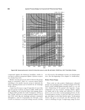
                 Figure 6-49. Typical  performance curves for rotary lobe vacuum  pump.  By permission, Tuthill Corp., M.D.  Pneumatics,  Division.
             compressed  against  the  discharge  headplate,  similar  in   are referenced to the indicated vacuum, not absolute pres-
             concept to a piston compressor against a piston compres-   sure.  (See the beginning of this chapter for clarification).
             sor cylinder head  [21].
               Booster vacuum pumps  are used  to shorten the pump-   Rotary Piston Pumps
             down  on  evacuation  (time)  of a  vacuum  system  before
             switching  to  the  smaller vacuum  pump  to  maintain  the   These  units  are  also  positive  displacement  oil-sealed
             system  opening vacuum  and  to  handle  the  air inleakage   pumps.  The pumping action is shown in Figure 6--50. The
             to  the system.                                      action  of the  rotating piston assembly  draws  in a  set vol-
               A typical performance range of  capacities of rotary lobe   ume  (depending  on  the  pump's  size/capacity)  of gas,
             vacuum  pumps  is  shown  in  Figures  6-48A,  6-48B  and  6-   compresses  it in  the  eccentric  rotating  cylinder against
             48C.  Another set of curves for rotary lobe pumps,  shown   the  inside  wall  of the  casing,  and  exhausts  it to  atmos-
             in  Figure  6-49,  provides  the  brake  horsepower,  airflow  at   phere,  as do most other vacuum pumping devices. AE.  the
             inlet (CFM)  (referred to as their standard volume at 70°F   oil-sealed piston revolves,  it opens  the inlet port,  draws  in
             and  29.92  inch  Hg  abs  discharge  pressure-essentially   gas,  and  traps  it in  the fixed suction space.  As  the  piston
             atmosphere),  and  the  temperature  rise  through  a  non-   rotates,  the  gas  is  compressed,  and  the  discharge  valve
             cooled  (no internal or external cooling)  vacuum. All data   opens to discharge the gas.  A single-stage pump can have
   425   426   427   428   429   430   431   432   433   434   435