
Page 429 - APPLIED PROCESS DESIGN FOR CHEMICAL AND PETROCHEMICAL PLANTS, Volume 1, 3rd Edition
P. 429
Ejectors and Mechanical Vacuum Systems 395
20 30
' i I ............
c, 20
18 iii I r,,,.,.,,.
l c..
I Pressure capability l
E 10
16 ::, for
! Ill
Ill
14 5- 5 rotary lobe blowers
.5! Cl)
� e>
al
c: 12 .c:
e
·;;; I "
Ill
Ill c
� 10 I
a. I 1 .
E 50 100 500 1,000 5,000 10,000 50,000
0
o 8 Inlet volume - CFM
high vacuum
6 boosters 22 I
I Ii I I I E 20
::,
4 i:l 18
i � 16
i \
2 b, 14 Vacuum capability
I
50 100 500 1,000 5,000 10,000 30,000 ! 12 I I I I II f l I I II '
11 or
Gross displacement - CFM 1! 10 rotary lobe blowers ,
"
-= 8
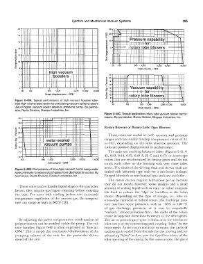
Figure 6-48A. Typical performance of high vacuum booster lobe- 6 11 I I . I
I
I
type high volume draw-down for evacuating vacuum systems before 50 100 500 1,000 5,000 10,000 50,000
use of higher vacuum (lower absolute pressure) pump. By pennis- Inlet volume - CFM
sion, Roots Division, Dresser Industries, Inc.
Figure 6-48C. Typical application rotary lobe vacuum blower perfor-
mance. By permission, Roots Division, Dresser Industries, Inc.
28
26
E 24 Rotary Blowers or Rotary Lobe-Type Blowers
::,
::, 22
"
"'
:,. ' These units are useful in both vacuum and pressure
"'
:c 20 water-sealed ranges and can usually develop compression ratios of 3:1
Ill 18 to 10:1, depending on the inlet absolute pressure. The
"
.c: vacuum pumps
" 16
-= units are positive displacement in performance.
14 The units use meshing balanced lobes (Figures 6-41, 6-
I 42, 6-43, 6-44, 6-45, 6-46 A, B, C and 6-47) or screw-type
12
100 500 1,000 5,000 10,000 30,000 rotors that are synchronized by timing gears and do not
lnlet volume - CFM touch each other or the housing with very close toler-
ances. The shafts of the driving shaft and driven shaft are
Figure 6-486. Perfcnnance of lobe-type vacuum pump using water
spray internally to reduce slip of gases from discharge to suction. By sealed with labyrinth type seals for a minimum leakage.
permission, Roots Division, Dresser Industries, Inc. Purged labyrinth or mechanical type seals are available.
The rotors do not require lubrication per se because
they do not touch; however, some designs add a small
These units cannot handle iiquid slugs or dirt particles; amount of sealing liquid such as water or other compati-
hence, they require gas/vapor cleaning before entering ble fluid to reduce the "slip" or backflow as the lobes
the unit. For units with cooiing jackets and automatic rotate. Depending on the type of design, i.e., lobe or
temperature regulation of the process gas, the tempera- screw-type cycloidal or helical rotors, the discharge pres-
ture can range as high as 302°F [20].
sure may have some pulsation, such as -60% to 140+%
of gas discharge pressure, or it may be essentially
"smooth," almost pulsation free. The shafts of the rotors
rotate .in opposite directions by means of the drive gears.
By adjusting the jacket temperatures, condensation or The air or process gas/vapor is drawn .into the suction or
polymerization can be avoided inside the pump. The vol- inlet cavity of the intersecting and rotating "lobes" by the
ume handled Figure 6-40 is often expressed as "free air, rotor mesh. As the rotors continue to rotate, the cavity of
CFM." This is simply the mechanical displacement of the suction gas is sealed from the inlet by the moving and/ or
pumping volume of the unit for the particular driven advancing "lobes" as they pass the fixed boundary of the
speed of the unit. inlet opening of the casing. AI; the rotors rotate, the gas is