
Page 434 - APPLIED PROCESS DESIGN FOR CHEMICAL AND PETROCHEMICAL PLANTS, Volume 1, 3rd Edition
P. 434
400 Applied Process Design for Chemical and Petrochemical Plants
pressure relieving devices be installed for pressure relief Types of Valves/Relief Devices
and venting per codes [1, 10, 13] [33].
Although not specifically recognized in the titles of the There are many design features and styles of safety
codes, the rupture disk as a relieving device, is, neverthe- relief valves, such as flanged ends, screwed ends, valves fit-
less, included in the requirements as an acceptable ted internally for corrosive service, high temperature ser-
device. vice, cryogenic service/low temperatures, with bonnet or
Usual practice is to use the terms safety valve or relief without, nozzle entrance or orifice entrance, and resis-
valve to indicate a relieving valve for system overpressure, tance to discharge piping strains on body. Yet most of
and this will be generally followed here. When specific these variations have little, if anything to do with the actu-
types of valves are significant, they will be emphasized. al performance to relieve overpressure in a system/vessel.
A few designs are important to the system arrangement
and relief performance:
Types of Positive Pressure Relieving Devices
(see manufacturers' catalogs for design details)
Conventional Safety Relief Valve
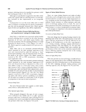
Relief Valve: a relief valve is an automatic spring loaded This valve design has the spring housing vented to the
pressure-relieving device actuated by the static pressure discharge side of the valve. The performance of the valve
upstream of the valve, and which opens further with upon relieving overpressures is directly affected by any
increase in pressure over the opening pressure. It is used changes in the back pressure on the valve ( opening pres-
primarily for liquid service [1,10] (Figure 7-lA and 7- sure, closing pressure, relieving capacity referenced to
lB). Rated capacity is usually attained at 25 percent over- opening pressure) [35]. See Figures 7-3, 7-6, and 7-6A.
pressure. When connected to a multiple relief valve manifold, the
Safety Valve: this is an automatic pressure-relieving performance of the valve can be somewhat unpredictable
device actuated by the static pressure upstream of the from a relieving capacity standpoint due to the varying
valve and characterized by rapid full opening or "pop" backpressure in the system.
action upon opening [l,10], but does not reseat. It is used
for steam or air service (Figure 7-2). Rated capacity is Balanced Safety Relief Valve
reached at 3%, 10% or 20% overpressure, depending
upon applicable code. This valve provides an internal design (usually bellows)
Safety-Relief Valve: this is an automatic pressure-relieving above/on the seating disk in the huddling chamber that
device actuated by the static pressure upstream of the minimizes the effect of backpressure on the performance
valve and characterized by an adjustment to allow reclo- of the valve (opening pressure, closing pressure and
sure, either a "pop" or a "non-pop" action, and a nozzle relieving capacity) [35]. See Figures 7-4, 7-6, and 7-6A.
type entrance; and it reseats as pressure drops. It is used
on steam, gas, vapor and liquid (with adjustments), and is
probably the most general type of valve in petrochemical
and chemical plants (Figures 7-3, 7-3A, and 7-4). Rated
capacity is reached at 3% or 10% overpressure, depend-
ing upon code and/or process conditions. It is suitable
for use either as a safety or a relief valve [1,10]. It opens
in proportion to increase in internal pressure.
Pressure Relief Valve
The term Pressure-relief valve applies to relief valves,
safety valves or safety-relief valves [10].
Piwt Operated Safety Valves
When properly designed, this type of valve arrange-
ment conforms to the ASME code. It is a pilot operated
pressure relief valve in which the major relieving device is
combined with and is controlled by a self-activating auxil- FLOW
iary pressure relief valve. See Figures 7-5A and B. Figure 7-1A. Relief valve. Courtesy of Crosby-Ashton Valve Co.