
Page 440 - APPLIED PROCESS DESIGN FOR CHEMICAL AND PETROCHEMICAL PLANTS, Volume 1, 3rd Edition
P. 440
406 Applied Process Design for Chemical and Petrochemical Plants
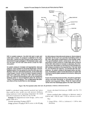
With no system pressure, the pilot inlet seat is open and As inlet pressure rises above set pressure, dome pressure
outlet seat is closed. As pressure is admitted to the main reduction will be such as to provide modulating action of
valve inlet, it enters the pilot through a filter screen and is the main valve piston proportional to the process upset.
transmitted through passages in the feedback piston, past The spool/feedback piston combination will move, re-
the inlet seat, into the main valve dome to close the main sponding to system pressure, to alternately allow pressure
valve piston. in the main valve dome to increase or decrease, thus mov-
ing the main valve piston to the exact lift that will keep sys-
As system pressure increases and approaches valve set tem pressure constant at the required flow. Full main valve
pressure, it acts upward on the sense diaphragm, with the lift, and therefore full capacity, is achieved with 5% over-
feedback piston moving upward to close the inlet ssat, thus pressure. As system pressure decreases below set pres-
sealing in the main valve dome pressure, as the outlet seat sure, the feedback piston moves downward and opens the
is also closed. A small, further increase in system pressure inlet seat to admit system pressure to the dome, closing the
opens the outlet seat, venting the main valve dome pres- main valve.
sure. This reduced dome pressure acts on the unbalanced
feedback piston to reduce feedback piston lift, tending to Due to the extremely small pilot flow, the pilot on gas/vapor
"lock in" the dome pressure. Thus, at any stable inlet pres- valves normally discharge to atmosphere through a
sure there will be no pilot flow (i.e. zero leakage). weather and bug-proof fitting. Pilots for liquid service
valves have their discharge piped to the main valve outlet.
Figure 7-5A. Pilot operated safety relief valve. By permission, Anderson, Greenwood and Co.
MAWP is calculated using nominal standard steel plates Assume calculated thickness per ASME code Par. UG-
(but could be other metal-use code stresses) thickness, 27: 0.43 in.
using maximum vessel operating temperature for metal Closest standard plate thickness to fabricate vessel is
stress determinations. See Ref [l] Par. UG-98. 0.50 in. with - 0.01 in. and + 0.02 in. tolerances at mill.
Example 7-l: Hypothetical vessel design, carbon steel
grade A-285, Gr C Then
Normal operating: 45 psig at 600°F 1. Using 0.50 in. - 0.01 in. (tolerance) = 0.49 in. min.
Design pressure: 65 psig at 700°F corres. to the 65 psig. thickness.