
Page 445 - APPLIED PROCESS DESIGN FOR CHEMICAL AND PETROCHEMICAL PLANTS, Volume 1, 3rd Edition
P. 445
Process Safety and Pressure-Relieving Devices 411
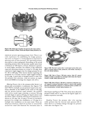
Figure 7-BA. Metal type frangible disk (above) with cross-section
(below) Courtesy of Black, Sivalls and Bryson Safety Systems, Inc.
maximum process operating pressure level. There is no
code requirement for establishing the design pressure.
(See chart in Chapter 1.) Good judgment is important in
selecting each of these pressures. See operating pressure
description in above paragraph. Depending on the actual
operating pressure level, the increase usually varies from
a minimum of 10% higher or 25 psi, whichever is greater,
to much higher increases. For instance, if the maximum Figure 7-88. Standard rupture disk. A prebulged rupture disk avail-
expected operating pressure in a vessel is 150 psig, then able in a broad range of sizes, pressures, and metals. Courtesy of
experience might suggest that the design pressure be set B.S. & B. Safety Systems.
for 187 to 200 psig. Other factors known regarding the
possibility of a run-away reaction might suggest setting it Figure 7-BC. Disk of Figure 7-88 after rupture. Note 30° angular
at 275 psig. A good deal of thought needs to enter into seating in holder is standard for prebulged solid metal disk. By per-
this pressure level selection. (Also see section on explo- mission, B.S.&B. Safety Systems, Inc.
sions and DIERS technology this chapter [55] [67] .)
Figure 7-BD. Disk of Figure 7-88 with an attached (underside) vacu-
Relieving Pressure: this is the pressure-relief device's set um support to prevent premature rupture in service with possible
pressure plus accumulation or overpressure. See Figures 7-7A less than atmospheric pressure on underside and/or pulsation ser-
and 7-7B. For example, at a set pressure equal to the max- vice. By permission, B.S.&B. Safety Systems, Inc.
imum allowable at the MAWP of the vessel of 100 psig,
and for process internal vessel pressure, the pressure this chapter and Figures 7-7B, 7-31A, B for these allowable
relief device would begin relieving at nominal l 00 psig pressure levels) and in no case do the figures apply to a
(actually begin to open at 98 psig, see figures above) and sudden explosion internally.
the device (valve) would be relieving at its maximum con-
ditions at 110 psig (the 10 psig is termed accumulation
pressure) for a single valve installation, or 116 psig, for a Resealing Pressure: the pressure after valve opening
multiple valve installation on the same vessel. These are under pressure that the internal static pressure falls to
all process situations, which do not have an external fire when there is no further leakage through the pressure
around the vessel (See External Fire discussion later in relief valve. See Figure 7-7A.