
Page 442 - APPLIED PROCESS DESIGN FOR CHEMICAL AND PETROCHEMICAL PLANTS, Volume 1, 3rd Edition
P. 442
408 Applied Process Design for Chemical and Petrochemical Plants
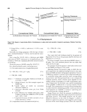
Opening Presssure
.... 100 100 100
Q)
::,
(J) 80 80 80 Closing Pressure
(J)
....
Q)
o,
Q)
Cl)
......
0
'#
Conventional Valve Conventional Valve Balanced Valve
(a) Backpressure Decreases Set Pressure (b) Backpressure Increases Set Pressure (c) Backpressure Has Little
Effect on Set Pressure
% of Backpressure
Figure 7-6A. Diagram of approximate effects of backpressure on safety relief valve operation. Adapted by pennission, Teledyne Farris Engi-
neering Co.
2. Using 0.50 in. + 0.02 in. (tolerance) = 0.52 in. max. P d = 2SEt/ (R - 0.4t) (7-3)
thickness.
Generally, for design purposes, with this type of toler- t = PR/[2SE + 0.4P] (7-4)
ance, nominal thickness = 0.50 in. can be used for calcu-
lations. The vessel shell wall thickness shall be the greater of
Now, using Par. UG-27, 0.50 in. thickness and ASME Equations 7-2 or 7-4, or the pressure shall be the lower of
code stress at 750°F (estimated or extrapolated) per Par. Equation 7-1 or 7-3 [l].
UCS-23 at 750°F, the maximum allowable stress in tension For above example assume calculated MAWP (above) =
is 12,100 psi. 80 psig. This is the maximum pressure that any safety relief
Recalculate pressure (MAivP) using Par. UG-27 [l] valve can be set to open.
For cylindrical shells under internal pressure: For pressure levels for pressure relief valves referenced
( 1) Circumferential stress (longitudinal joint) to this MAWP, see Figures 7-7A and B.
Operating Pressure: the pressure, psig, to which the ves-
sel is expected to be subjected during normal or, the max-
Pc1 = SEt/(R;+ 0.6t), psi= psig (7-1)
imum probable pressure during upset operations. There is
a difference between a pressure generated internally due
t = PR/ [SE - 0.6P] (7-2)
to controlled rising vapor pressure (and corresponding
temperature) and that generated due to an unexpected
where t = minimum actual plate thickness of shell, no runaway reaction, where reliance must depend on the
corrosion, = 0.50" sudden release of pressure at a code conformance pres-
P d = design pressure, for this example equals the sure/ temperature. In this latter case, careful examination
!vIAWP, psi of the possible conditions for a runaway reaction should
R, = inside radius of vessel, no corrosion be made. This examination is usually without backup data
allowance added, in. or a firm basis for calculating possible maximum internal
S = maximum allowable stress, psi, from Table vessel pressure to establish a maximum operating pres-
UCS-23 sure and from this, a design pressure.
E = joint efficiency for welded vessel joint, plate Design Pressure of a Vessel: the pressure established as a
to plate to heads. See ASME Par. UW-12, nom- nominal maximum above the expected process maximum
inal = 85% = 0.85 operating pressure. This design pressure can be estab-
t = required thickness of shell, exclusive of cor- lished by reference to the chart in Chapter 1, which is
rosion allowance, inches based on experience/practice and suggests a percentage
(2) Longitudinal stress (circumferentialjoints). increase of the vessel design pressure above the expected