
Page 477 - APPLIED PROCESS DESIGN FOR CHEMICAL AND PETROCHEMICAL PLANTS, Volume 1, 3rd Edition
P. 477
Process Safety and Pressure-Relieving Devices 443
"'""��t,c���-+.eo
l���===t:·711
••
.IO l
�...------t: n
���toc=====t: .. , W
� I
,.,,�111#,,"'4,�,rL-�������� ....
m�=============t ..
:.1
61'r,;!V':ll"'Jlf'7"-'.:.,....����������---t-.n �
J.!i"-'�:..._����������-t'"'
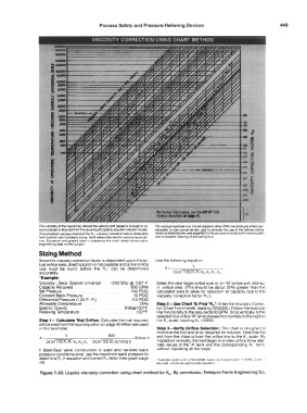
The voscos,ty ol the liquid may reduce the 119ioc1ty and capacity enough to re- For viscous hqurd service rt rs advisable to allow 25% overpressure where per-
quire a larger oriloce s,ze than the usuat l,quid capac,ty equation would ,ndocate m,ssable. to size conservanvetv. and lo consider lhe use of the bellows and/or
Tms s,mpl1hed voscos,ty chart and the ·K; viscostv correctoon factors obtainable steam 1ac1<.eted bodies (see page 63) for the purpose ol 1solat1n9 the moving parts
!rom 11 are tor use 1n properly swng relief val'o'e's intended for viscous liquid ser and to prevent lree,,ng of the lacllng llu1C!
111ce_ Equations and graphs used 1n prepanng lhts char! reflect conscrvanve
eng,neenng data on tho subject
Sizing Method
S,nce the viscosity correction factor is dependent upon the ac- Use the following equation
tual orifice area, direct solution rs not possible and a trial orifice v.
size must be found before the "Ku" can be determined A=��;::::====:=--����
accurately. 24.3¥ 1 25 P, -P, Kµ K� K., K,.
•example:
Viscosity- Secs. Say bolt Universal 1250 SSU @ 100° F Select the next larger orifice size. or an "M" orifice with 3.60 sq
Capacity Required 800 GPM in. orifice area. (This should be about 20% greater than the
Set Pressure .. 100 PSIG calculated area to allow for reduction of capacity due to the
Constant Back Pressure . . 10 PSIG viscosity correction factor "Ku")
Ditterent1al Pressure (1.25 P,-P2) .115 PSIG
Allowable Overpressure 25% Step 2-Use Chart To Find "Ku": Enter the v.scosny Correc-
Specific Gravify . 0.98@100°F tion Chart from the left. reading 1250 SSU. Follow the example
Relieving Temperature 100°F line horizontally to the required 800 GPM Drop vertically to the
selected trial orifice "'M" and proceed horizontally to the right to
Step 1- Calculate "'Dial Orifice: Calculate the trial required the Ku scale, reading K 0 = 0.955.
orifice area from the liquid equation on page 40 (Alternate used
in this example). Step 3-Vertty Orifice Selection: This chart is designed 10
minimize the trial and error required for solution. Note that the
A� V1 BOO - = 304sq 1n exit from the chart is from the orifice line to the K,. scale By
243¥125 P,-P? Kp Kq Ku 243¥ 125-10 (1)(1.010)(1) inspection vertically, the next larger or smaller orifice show alter
nate values of the "A" term and the corresponding ''K,." term.
If BalanSeal valve construction rs used and variable back without repeating all the steps.
pressure conditions exist. use the maximum back pressure to
determine P 0 in equation and correct Kw factor (see graph page 'Exampte given 1::; tor a non-ASME Code l:qu1d aupucauon H ASME Code �.
44) recurred sunstuure apnropnate equation
Figure 7-23. Liquids viscosity correction using chart method for K.,. By pennission, Teledyne Farris Engineering Co.