Page 474 - APPLIED PROCESS DESIGN FOR CHEMICAL AND PETROCHEMICAL PLANTS, Volume 1, 3rd Edition
P. 474

440                      Applied  Process Design for Chemical and  Petrochemical  Plants


                 0.60                  1 k � I                           Vl ma.�   =  maximum mass flow at critical or choked
                     \         I   I  2                                         conditions,  lb/sec
                                                                          1
                 059         Pc  /P  • (k+I)   1   I
                       \                                              Pc= Pcrit  =  critical flow throat pressure, psia =  sonic  =
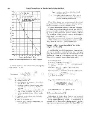
                 0.58        Pc  = Critical  Pressure, psi  a.                  choked pressure  =  maximum downstream
                        \    P  • Total Absolute  Pressure  Upstream            pressure producing maximum flow
                 0.57           of Safety  Valve  at Full  Relief, _
                          \     Equals  Set  Pressure  pkJs
                 Q56            Overpressure  , psla.               When/if the downstream  pressure exceeds the critical
                            \                                     flow pressure, then sub-critical pressure will occur and the
                 0.55
                              \                                   equations for sub-critical flow should be used.
                a. 0.54        I\                                   When the downstream pressure is less  than  ( or below)
                .....
                a."             \                                 the critical or choked pressure,  the velocity and fluid flow
                 • 0.53                                           rate at a restriction or throat will not/  cannot be increased
                .s                '  \
                ..                   \                            fluid velocity at the restriction or throat is  the velocity of
                �   Q52                                           by  lowering  the  downstream  pressure  further,  and  the
                ..   I                                            sound at the conditions  [29].
                �  0.5
                .t 0.50                I\                           The critical or sonic ratio is conveniently shown on Fig-
                                          \
                .;                         �                      ure  7-21, but this  does  not eliminate  the need for calcu-
                := 0.49                                           lating the PJP1  ratio for a more accurate result.
                ·.:::                       \
                u
                 0118                           -,                Example 7-2: Flow through Sharp Edged Vent Orifice
                  0117                                            (adapted after Ref.  [29])
                                                  I\
                  0116
                                                    '\              A small hole bas been deliberately placed in a vessel near
                  0!45                                I\          the  top  to  provide  a  controlled  vent  for  a  nitrogen
                                                       \          purge/blanket. The hole is 0.2-inch diameter with the vessel
                  0·4 \o   I.I   1.2   1.3   1.4   1.5   1.6   1.7   1.8   1.9   2.0   operating at 150 psig at 100°F.  Determine the flow through
                            Ratio  of Specific  Heats, k = Cp/Cv   this vent hole. Assume it acts as a sharp edged orifice.
              Figure 7-21. Critical  backpressure ratio for vapors and gases.
                                                                    k  (for nitrogen)  =  1.4
                                                                    Pc/P1  =  See Equation 7-7  [2/(k +  l)Jk/k  - 1
                                                                                                  1
                                                                    Pc= (150  +  14.7)  (2/1.4 +  ])l.4/1.4  -  =  86.9 psia,  critical
               At critical  conditions,  the  maximum flow  through  the   pressure
                                                                                               2
                                                                                     2
            nozzle or orifice is:  [29]                             Hole area= A= 1t  d /4 =  1t  (0.2) /4 =  0.0314 sq in.
                                                                             =  0.0002181  sq ft
                                                                    Discharge coef,  (\ =  assumed =  1.0  (Note, could calculate
                                                                                     Re  to verify.)
               \V max  (crirical now)  = Co AP o          (7- 9)    Inside pressure= 150 psig +  14.7  =  164.7 psia
                                                                    T 0   =  100 +  460  =  560°R

            where     M  =  mo! wt of vapor or gas
                                       0
                      TO  =  temp of service,  R                    v\lma,  =  [1.0 (0.0002181)(164.7)(144sq in./sq  ft)]
                      Rg  =  ideal universal gas constant =  1544,  ft lb/lb-   [   [  (1.4)(32.12)(28)](-2-)(l. 4+l)/(l.-1-l)  l
                          mol-0R,  also= MR
                      C =  discharge coefficient for sharp-edged orifice    -�   ( 1545 ) ( 560 )   1.4 + 1
                       0
                          =  0.61  for Reynolds Number> 30,000 and
                          not sonic
                      C =  1.0 for sonic flow,  C increases from 0.61  to 1.0.   critical flow rate, Wma.x  =  0.002518 lb/sec
                       0
                                         0
                          Use 1.0 Lo be conservative  [29]  [36]. 5th Ed.]
                      A  =  area of opening,  orifice, or hole, or nozzle,   Orifice Area Calculations [68]
                          sq.  ft.
                  P 1  =  P =  upstream pressure, lb/sq foot,  abs,  (psfa)   Calculations  of  Orifice  Flow  Area  for  Conventional
                       0
                       g  =  32.12 ft/sec/sec                     Pressure  Relieving  Valves,  and  Flow  is  Critical  (sonic)
                      M  =  mo!.  wt.  of vapor or gas            Through  Part  of Relieving  System,  i.e.,  backpressure  is
                       �  =  ratio of orifice diameter/pipe diameter (or   less  than 55%  of the absolute  relieving pressure  (includ-
                          nozzle inlet diameter)                  ing set pressure plus accumulation). See Figure 7-7A,  use
   469   470   471   472   473   474   475   476   477   478   479