
Page 478 - APPLIED PROCESS DESIGN FOR CHEMICAL AND PETROCHEMICAL PLANTS, Volume 1, 3rd Edition
P. 478
444 Applied Process Design for Chemical and Petrochemical Plants
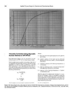
Viscosity Correction Using Reynold's Where:
Number Method of API RP520 VL = flow rate at the flowing temperature in U.S. gallons
per minute.
As an alternate to Figure 7-23, you may wish to use the G = specific gravity of the liquid at the following
method given in API RP 520 for sizing viscous liquids. temperature referred to water= 1.00 at 70 degrees
Fahrenheit.
When a relief valve is sized for viscous liquid service, it
is suggested that it be sized first as for nonviscous type µ = absolute viscosity at the flowing temperature. in
application in order to obtain a preliminary required centipoises.
discharge area. A From manufacturer's standard ori-
fice sizes. the next larger orifice size should be used in A= effective discharge area. in square inches (from
determining the Reynolds number R, from either of the manufacturers' standard orifice areas).
following relationships:
U = viscosity at the flowing temperature, in Saybolt
Universal seconds.
R = VL(2,800 G)
µVA After the value of R is determined. the factor Kv tis ob·
tained from the graph. Factor Kv is applied to correct the
or "preliminary required discharge area" If the corrected
area exceeds the "chosen standard orifice area", the
.R = 12,700 VL above calculations should be repeated using the next
u\,/'j\ larger standard orifice size.
'Use ot ttus equation rs not recommended for viscosnies less than 100 SSU I K, of AP! = K, of Teledyne Fams
Figure 7-24. Viscous liquid valve sizing using the method of API RP-520. Reprinted by permission, Teledyne Farris Engineering Co. and Siz-
ing, Selection and Installation of Pressure-Relieving Devices in Refineries, Part I "Sizing and Selection," API RP-520, 5th Ed., July 1990, Amer-
ican Petroleum Institute.