
Page 476 - APPLIED PROCESS DESIGN FOR CHEMICAL AND PETROCHEMICAL PLANTS, Volume 1, 3rd Edition
P. 476
442 Applied Process Design for Chemical and Petrochemical Plants
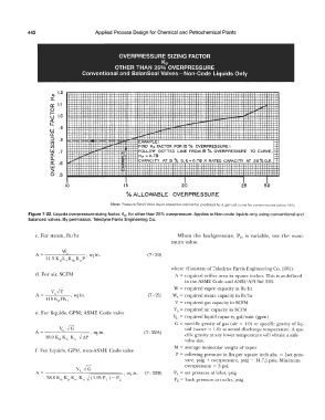
OVERPRESSURE SIZING FACTOR
Kp
OTHER THAN 25% OVERPRESSURE
Conventional and BalanSeal Valves- Non-Code Liquids Only
1.2
D..
x
a:: I.I -
f2
o 1.0
�
w .9
a::
::> .8
(/) EXAMPLE,
(/) FIND Kp FACTOR FOR 15 "lo OVERPRESSURE:
w .7 FOLLOW DOTTED LINE FROM 15 % OVERPRESSURE TO CURVE.
a: Kp =0.79
0.. CAPACITY AT 15 'ro O. P. = 0. 79 X RATED CAPACITY AT 25 % O.P.
0:: .6
w
>
0 .5
10 15 20 25 50
% ALLOWABLE OVERPRESSURE
Note: Pressure Relief Valve liquid capacities cannot be predicted by a general curve for overpressures below 100: 0
Figure 7-22. Liquids overpressure sizing factor, Kp, for other than 25% overpressure. Applies to Non-code liquids only using conventional and
balanced valves. By permission, Teledyne Farris Engineering Co.
c. For steam, lb/hr When the backpressure, P2, is variable, use the maxi-
mum value.
(7 - 20)
where (Courtesy of Teledyne Farris Engineering Co. [68]):
d. For air, SCFM A = required orifice area in square inches. This is as defined
in the ASME Code and A.t'-l'SI/ AP! Std 526.
W = required vapor capacity in lb/hr
(7 - 21) W = required steam capacity in lb/hr
5
V = required gas capacity in SCFM
v. = required air capacity in SCFM
e. For liquids, GPM; ASME Code valve
VL = required liquid capacity, gal/min (gpm)
G = specific gravity of gas (air = 1.0) or specific gravity of liq-
VL {G uid (water = 1.0) at actual discharge temperature. A spe-
A = sq in. (7- 22A)
--------,.-;:p-, cific gravity at any lower temperature will obtain a safe
38.0 x, K" Ku -V CH'
valve size.
M = average molecular weight of vapor
f. For liquids, GPM, non-ASME Code valve
P = relieving pressure in lbs per square inch abs. = [set pres-
sure, psig + overpressure, psig + 14.7,J psia. Minimum
overpressure = 3 psi.
P 1 = set pressure at inlet, psig
P2 = back pressure at outlet, psig