
Page 479 - APPLIED PROCESS DESIGN FOR CHEMICAL AND PETROCHEMICAL PLANTS, Volume 1, 3rd Edition
P. 479
Process Safety and Pressure-Relieving Devices 445
.1.P = Set pressure + overpressure, psig - back pressure, psig. 0.62 for rupture disks and non-reclosing spring loaded
AL 10% overpressure delta P equals 1.1 P 1 - P 2• Below devices; ASME [I], Par. UG-127.
30 psig set pressure, delta P = P1 + 3 - P2. **0.975 per AP! RP-520, balanced valves
T = inlet temperature °F absolute = (°F plus 460)
Where the pressure relief valve is used in series with a
Z = compressibility factor corresponding to T and P. If this rupture disk, a combination capacity of 0.8 must be applied
factor is not available, compressibility correction can be to the denominator of the referenced equations. Refer to a
safely ignored by using a value of Z = 1.0.
later section this text or to specific manufacturers.
C = gas or vapor flow constant, see Figure 7-25.
k = ratio of specific heats, Cp/C, .. If a value is not known the **Some manufacturers' National Board Certified Tests
use of k = 1.001, C = 315 will result in a safe valve size. will have different values for some of their valves. Be sure
!sen tropic coefficient, n , may be used instead of k. Lo obtain the manufacturer's certified coefficient for the
valve you select.
� = liquid capacity correction factor for overpressures lower
than 25% for non-code liquids equations only, (see Fig-
ure 7-22). Sizing Valve for Liquid Expansion (Hydraulic Expansion of
Kb = vapor or gas flow correction factor for constant back Liquid Filled Systems/Equipment/Piping)
pressures above critical pressure (see Figure 7-26).
K, = vapor or gas flow factor for variable back pressures for The API Code RP-520 [33a] suggests the following to
balanced seal valves only (see Figure 7-27A and Figure 7- determine the liquid expansion rate to protect liquid-
27B). filled (full) systems or locations where liquid could be
K,,. = liquid flow factor for variable back pressures for balanced trapped in parts of a system or an area could be subject to
seal valves only (see Figure 7-28). For atmos., K; = 1.0. blockage by process or operational accident. When ther-
Ku = liquid viscosity correction factor (see Figures 7-23 or Fig- mal input from any source can/ could cause thermal
ure 7-24). expansion of the enclosed liquid:
K,,h = steam superheat correction factor (see Table 7-7).
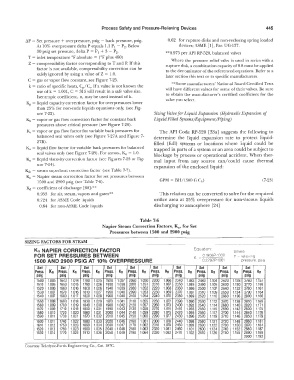
Kn = Napier steam correction factor for set pressures between
1500 and 2900 psig (see Table 7-6). GPM = BH/ (500 G Ch) (7-23)
Kc!= coefficient of discharge [68] :**
0.953 for air, steam, vapors and gases** This relation can be converted to solve for the required
0.724 for ASME Code liquids orifice area at 25% overpressure for non-viscous liquids
0.64 for non-ASME Code liquids discharging to atmosphere [24]
Table 7-6
Napier Steam Correction Factors, Kn, for Set
Pressures between 1500 and 2900 psig
SIZING FACTORS FOR STEAM
Kn NAPIER CORRECTION FACTOR Equation: Where
FOR SET PRESSURES BETWEEN 0.1906P·1000 P = relieving
1500 AND 2900 PSIG AT 100/o OVERPRESSURE K = 0 2292P·1061 pressure. psia
-
Set Set Set Set Set Set Set Set Set Set
Press. Kn Press. Kn Press. Kn Press. Kn Press. Kn Press. Kn Press. Kn Press. Kn Press. Kn Press. Kn
pslg psig psig psig psig pslg psig psig psig psig
1500 1.005 1640 1.014 1780 1.025 1920 1.037 2060 1050 2200 1.066 2340 1.083 2480 1.104 2620 1.128 2760 1.157
1510 1.005 1650 1.015 1790 1.026 1930 1.038 2070 1.051 2210 1.067 2350 1.085 2490 1.105 2630 1.130 2770 1.159
1520 1.006 1660 1.016 1800 1.026 1940 1.039 2080 1.052 2220 1.068 2360 1.086 2500 1.107 2640 1.132 2780 1.161
1530 1.007 16i'O 1.016 1810 1.027 1950 1.040 2090 1.053 2230 1.069 2370 1.087 2510 1.109 2650 1.134 2790 1.164
1540 1.007 1680 1.017 1820 1.028 1960 1.040 2100 1.054 2240 1.070 2380 1.089 2520 1110 2660 1.136 2800 1.166
1550 1.008 1690 1.018 1830 1.029 1970 1.041 2110 1.055 2250 1.072 2390 1.090 2530 li12 2670 1.138 2810 1.169
1560 1.009 1700 1.019 1840 1.030 1980 1.042 2120 1.057 2260 1.073 2400 1.092 2540 1.114 2680 1140 2820 1.171
1570 1009 1710 1.019 1850 1.031 1990 1.043 2130 1.058 2270 1.074 2410 1.093 2550 1.115 2690 1.142 2830 1.174
1580 1.010 1720 1020 1860 1.031 2000 1.044 2140 1.059 2280 1.075 2420 1.095 2560 1.117 2700 1144 2840 1.176
1590 1.011 1730 1.021 1870 1.032 2010 1.045 2150 1.060 2290 1.077 2430 1.096 2570 1.119 2710 1146 2850 1.179
1600 1.011 1740 1.022 1880 1.033 2020 1.046 2160 1.061 2300 1.078 2440 1.098 2580 1.121 2720 1148 2860 1.181
1610 1.012 1750 1.023 1890 1034 2030 1.047 2170 1.062 2310 1.079 2450 1.099 2590 1.122 2730 1150 2870 1.184
i
1620 1.013 1760 1.023 1900 1.035 2040 1.048 2180 1063 2320 1.081 2460 1.101 2600 1:124 2740 1152 2880 1.187
1630 11.014 1770 1.024 1910 1.036 2050 1.049 2190 1.064 2330 1.082 2470 1.102 2610 1.126 2750 1.155 2890 1.189
2900 1.192
Courtesy Teledyne-Farris Engineering Co., Cat. 187C.