
Page 484 - APPLIED PROCESS DESIGN FOR CHEMICAL AND PETROCHEMICAL PLANTS, Volume 1, 3rd Edition
P. 484
450 Applied Process Design for Chemical and Petrochemical Plants
SpGr = specific gravity referred to air = 1.0. rupture disk may perform a vital safety relief function.
r = ratio of backpressure to upstream relieving Sometimes the combination of a rupture disk and pres-
pressure, P 2 /P sure-relieving valve will satisfy a prescribed situation, but
the valve cannot be relied on for instantaneous release
Emergency Pressure Relief: Fires and Explosions (response time lag of usually a few seconds).
Rupture Disks The ASME Pressure Vessel Code [ l] and the API codes
or recommended procedures [10, 13, 33] recognize and
Process systems can develop pressure conditions that set regulations and procedures for capacity design, man-
cannot timely or adequately be relieved by pressure-reliev- ufacture and installation of rupture disks, once the user
ing valves as described earlier. These conditions are pri- has established the basis of capacity requirements.
marily considered to be ( 1) internal process explosions
due to runaway reactions (see DIERS [67]) in pressure External Fires
vessels or similar containers such as an atmospheric grain
storage silo (dust explosion typically) or storage bin; (2) There have been at least six different formulas pro-
external fires developed around, under, or encompassing posed and used to determine the proper and adequate
a single process vessel or a system of process equipment, size of rupture disk openings for a specific relieving con-
or an entire plant; and (3) other conditions in which dition. The earlier studies of Sylvander and Katz [25] led
rapid/instantaneous release of developed pressure and to the development of the ASME and API recommenda-
large volumes of vapor/liquid mixture is vital to preserve tions. This approach assumes that a fire exists under or
the integrity of the equipment. For these conditions, a around the various vessels in a process. This fire may have
1.0 -
...
-...-, ·- ""
...-::...- ',!': "-"
..... .,".J,
.........
.... ',!': .... , I, .,
.... _.,
I/
....
-" .,
.....
0.9 - .... """' - ..
.. .. .,
...-i.,,,.,.. � .... ., �
,- ..... .. ·., ... .. ., ; ,
I.; ,_,,,. .... ..I .,
I/ .... ,,
..... '"' .... ., .... � "',, .,
... .,
I, ,
,
I, "' ..I , .... ,., I.,' ..... v !;'
....
., , .... ,, L,
., "' ., ., ., ....
I,
,,. .... ..... ., "' _., I, .. i.., .,
0.8 _,,,. .... .... "' ,,
,
., - _., _., _., I, i..,
',!': , ., .... .... ... ., I/
., .... ,, ,., ,., ., ,
.... ..... , ., ., ... ., l/
.,,
, .... _,,,. i.., ., ., � ., I,'
., .... .... ... ,., , ,, ,
,
, .... ., ., ... "' , , ,
.....
r- .... ,., .,
...... - <o i.., ,
,-,-
0.7 - � ...... - 'v<a - \)< "' �- "'
___ ,...
""'
// - ,. -
'1;,
�- -.{!->- ''" ----· o' - -CRITICAL FLOW LI NE
-- a
,, .....
� -- />·
I-
I
"" I
I I
0.6 I I
0.4 0.5 0,6 0.8 0.9 1.0
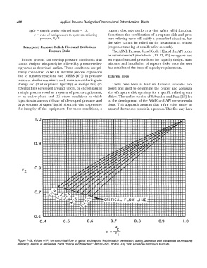
Figure 7-29. Values of F 2 for subcritical flow of gases and vapors. Reprinted by permission, Sizing, Selection and Installation of Pressure-
Relieving Devices in Refineries, Part I "Sizing and Selection," API RP-520, 5th Ed. July 1990 American Petroleum Institute.