Page 483 - APPLIED PROCESS DESIGN FOR CHEMICAL AND PETROCHEMICAL PLANTS, Volume 1, 3rd Edition
P. 483

Process Safety and Pressure-Relieving  Devices                       449


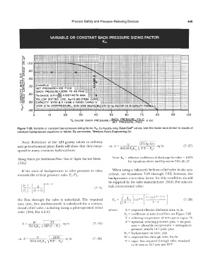
                               VARIABLE OR CONSTANT BACK  PRESSURE SIZING  FACTOR
                                                              Kw


               Cl.                                                               -                            -  --
                                                                                                                ·-
               <I
               z                                                                                 ;   I•
               0   1.00
               0
               LL.I
               en   .90                                                                      '.
             a.;  c(                                                                             '  .
              .  (I)           -                                                                ';              -
             ID                                                                                 .             ........ _
               >-
             :Z:t-   . 80
             1--       J                                                                                  ·-  ---··
                                                                                                             -·-
             -u
             ��   .70   EXAMPLE:               -                                                           -- ·-
                                                                                                                -
             >-  c(    SET  PRESSURE= 100  PSIG                                                          '.
             1-u       BACK  PRESSURE= ZERO  TO  40  PSIG                                        '   .  '
             iJ:::)   . 60     B.P.= � XI00=40%                                                      .  '.
             �w        %GAUGE                    MAX  .                     - -                -    .  '
             c(  ....   FOLLOW  DOTTED  LINE. Kw=0.88  (FR:>M  CURVE)
             u�   .50   CAPACITY  WITH  B.P.  =0.88 X  RATED  CAPACIT:t'                                       ---
              II      .  (FOR  10 %  OVERPRESSURE, NON-CODE VALVES, MULTIPY BY Kp  FACTOR  0.6 IN CAPACITY FORMULA)
              �  �                                                                    : -r-:-,
                  .40          I        I        I                 I        I        I
                               '
                     0        10       20       30       40       50       60       70        80       90       100
                                           %  GAUGE  BACK  PRESSURE= BACK  PRESSURE, p SIG  X  100
                                                                    SET  PRESSURE,PSIG
            Figure  7-28. Variable or constant backpressure  sizing factor,  Kw,  for liquids only,  BalanSeal®  valves.  Use this factor as a  divisor to results of
            constant backpressure equations or tables.  By permission, Teledyne Farris Engineering Co.
              Note:  Reference  of the  A.PI  gravity values  to  refinery          /ZT(Sp
                                                                       _
                                                                                                 .
            and petrochemical  plant fluids will  show  that they corre-   or,  1  \ -   V   Gr)  ,  sq m.    (7 - 27)
                                                                         863. 63 F 2 Kd  \  P(P -  P 2)
            spond  to many common hydrocarbons.
            Sizing Valves for Subcriiical Flow:  Gas  or Vap01;  but not Steam   Note:  K,i  = effective coefficient  of  discharge for valve= 0.975
            [33AI                                                            for equations above and Equations 7-25, 26,  27
              If the  ratio  of backpressure  to  inlet pressure  to  valve   When using a balanced/bellows  relief valve in the sub-
            exceeds the critical  pressure  ratio, Pc/P 1,        critical,  use  Equations  7-18  through  7-22;  however,  the
                                                                  backpressure  correction factor for this  condition  should
                                                                  be supplied by the valve manufacturer [33A). For sub-crit-
                                                                  ical,  conventional valve:
                                                         (7 - 7)

                                                                         /(           .    (r)(k-lJ/k]
                                                                                J
                                                                             k
            the  flow  through  the  valve  is  subcritical.  The  required   Fo  =   -- (r)2!k  [  J  -      (7 - 28)
            area  (net,  free  unobstructed)  is  calculated for a  conven-   ·   �    k-1   1-r
            tional  relief valve,  including sizing a pilot-operated relief
            valve  [33A,  Par 4.3.3):                             where:    A  =  required effective discharge area,  sq in.
                                                                           F 2  =  coefficient of subcritical  flow,  see Figure 7-29
                                                                                                                 0
                                                                            T =  relieving temperature of inlet gas or vapor,  R
                                                                            P  =  upstream relieving pressure,  psia,  =  set pres-
                                                         (7 - 25)
                                                                               sure + allowable overpressure  +  atmospheric
                                                                               pressure, usually  14. 7 psia), psia
                                                                           P 2  =  backpressure on valve,  psia
                              I                                            W  =  required  flow  through valve, lbs/hr
            or,  A =   V      /   ZTM   sq  in           (7 - 26)
                   4645.2I�K<l  V  P(P-P 2) 1   •                           V  = vapor flow required through valve,  standard
                                                                               cu ft/min at 14.7 psia and 60°F
   478   479   480   481   482   483   484   485   486   487   488