Page 487 - APPLIED PROCESS DESIGN FOR CHEMICAL AND PETROCHEMICAL PLANTS, Volume 1, 3rd Edition
P. 487

Process Safety and Pressure-Relieving Devices                       453

                                                                                                  ,.
                                                                                                 /
                                                                                                   I   I
                                                                                               /       I
                                                                                             7     I   I
                                                                                                       i


                                                                                                       I
                                                                                                       I
                 1,000
                    8
               -    6  1-----1---1--i---i-----l--+--1-+-il-----l-"�I/   /   I   �/--+---l---,4- / --+--+-l-+++----1--+--1---1--1--1--1-�
               N
                                                               .,._-;;./
                                                                            /
                                                   'o/
                    5  1-----+---+--i---i-----l--+--1-�1----·t,   /   "�---+---+-t'--+-+-+-+-i-+-1----+--l---+--i--+-+-+-H
                0
                e    ,__  __ _ _,___,___,_...__,_,_,'--�  �  ..  �':;   /   �  ..  � ..-+-/r---+--,,. � /--l-l-l-t-+++-----1---+--i---+-i---+-,H-i
                               _._
                           _._
                ..
                                                            �/
                                               't,�",
                                                                        /_
               <(   4                         �-/     /    �'A-+-1--l----H'-r-'-_,__--'--'-..L-J....L..Jl-----'--'--....l-.--l-....L...l....J..-'-j
                                                                                    I
                                                                v
                u
                                                     v
                                                          �
                                                                       /
               .!!   3                     .s:  1   /   � /,, � _r+++-+----,'-- / 1---l  Noles: Based  on  API  RP-520, 1988
                ..                               V     �/                      On  Insulated  Vessels  Insulation  sho!I  resist
                a,
               (/)   2                                                         Q:  21,000 FA·82
                ..                  I   <>)  �r  ·   .s-  .f:!"1./   �.,.,"   I   Dislodgement  by  Fire  Hose  Streams .
               -0                                     c
                                           �
                                                     :/
                                              "'
                                       �
               3C                    � " � "-                  ·1              Surface  Area  shell include only  Totally
                                                                               Wetted  Surface  within  a  Height  of  2!)  ft.
                           �  _
                  100  ,__  __   _.__....  _  _.. i   ..  �   ·,$,·1   ,"
                                   � ,::/ �� ,.... ....  v..;:i
               <(                               � .}: . ,./_/--+--<-<-  <o.,   .,.._....._  __  ,___.   Above  Grade  or in  the  Case  of Spheres  or
                    e  1-----+-·-+--+-"         �,                             Spheroids  to  the  Elevation  of  :he
                                  "-1     I    ..;:.1       /                  Maximum  Horizontal Diameter.
                    6
                                               /
                    5  1----+---' ,.!$'�/   ,'-'  v   /   /  i/                The  term  Grade  usually  Refers  lo  Ground
                               .,W
                              '}�
                    4  1-----+---   /      V          /                        Grade  but  may  be  any  Level at  which  a
                                                                               Sizable  Area  of  Exposed  Flammable
                                      I   7          /                         Liquid  may  be  Present.
                           /      / I  1   /       /                           For  Flom ma ble  Insulation  use  F  =  1.0  or
                   2       1     ,,     1                                      Bare  Vessel  Equivalent.
                   tQ �� � '-- -3 � l/---"4<.-'. / � -6L/..L.J8-LI- �� '-- �� '----1.3-4.,__5'--'6-'-·8L..L...L----'-2--'- 3 --1.4--L5-L6.J-J8L....W---2'----1.3_L 4 -L 5 � 6-L � 8..W  I
                        -__.., 2
                             -
                   10,00C                100,000              1,000,000            10,000,000          100,000,000
                                                   O  : Heat  Absorbed, BTU I Hr.
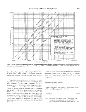
            Figure 7-30. API fonnula for heat absorbed from fire on wetted surface of pressure vessel. Prepared by pennission, Sizing, Selection and Instal-
           lation of  Pressure  Relieving Devices in Refineries,  Part I  "Sizing and Seiection," API  RP-520,  5th  Ed. July 1990, American  Petroleum Institute.
            the walls and be evaporated only as long as there is liquid   Each  situation  must be  evaluated  on its  own  merits  or
            to  drain  off  the  trays,  but for  a  conservative  approach,   conditions and  operating situation,  and  even its environ-
            assume that there are always wetted walls in the column.   ment  with  respect  to  the  plant  flammable  processing
                                                                  equipment.
              For packed columns,  the wetted walls are at least to the
            top  of the  packing,  with  some  entrainment height above   Relief  Capacity for Fire Exposure
            that.  Therefore,  a  vertical  packed  column  of 60  feet of
            packing  above  the  liquid  level  in  the  sump,  which  has  a
            sump of 10 feet and a skirt of 10 feet, would be considered   In  calculating  the  relief capacity  to  take  care  of exter-
            70 feet of vertical  height of wetted  perimeter,  not count-   nal  fire the following equation is used:
            ing  the skirt.  If the wetted area reached a  total  height of
            80 feet from  grade,  minus  the unwetted area of the skirt
            height,  because no liquid is in  the skirt space,  the 80 feet   W= Q/L                           (7-31)
            would  not be used to  establish  the vertical  height for fire
            exposure,  but use 60 ft  +  10 ft,  or 70 feet wetted  height.
            This  is  more  conservative  than  code  [33a  and  c], but is   where  W =  weight rate of flow of vapors,  pounds per hour
            based  on  experience  in  investigating  the  damage  levels   L =  latent heat at allowable pressure, BTU/lb
            from fires.                                                Q =  total heat absorption  from external fire, BTU/hr
   482   483   484   485   486   487   488   489   490   491   492