
Page 541 - APPLIED PROCESS DESIGN FOR CHEMICAL AND PETROCHEMICAL PLANTS, Volume 1, 3rd Edition
P. 541
Applied Process Design 507
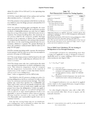
where R is either 9.0 or 10.0 and T; is the operating tem- Table 7-27
perature in C. Fuel Characteristic Constant for Venting Equation
5-3.3.3 For vessels fabricated of low carbon steel and low Fuel C(psi)112 C(kPa)1;2
alloy stainless steel Fu = 4.0 and FY = 2.0. Anhydrous Ammonia 0.05 0.13
Methane 0.14 0.37
5-3.4 The presence of any pressure relief device on the sys- Gases with fundamental
tem shall not cause the design pressure calculated by 5-3.3 burning velocity less than
to be reduced. 1.3 times that of propane 0.17 0.45
St-I dusts 0.10 0.26
5-3.5* For systems handling gases and liquids, the maxi- St-2 dusts 0.12 0.30
mum initial pressure, Pi, shall be the maximum pressure St-3 dusts 0.20 0.51
at which a combustible mixture can exist, but not higher
than the setting of the pressure relief device plus its accu- Supporting material on explosion protection methods against dust
mulation. For systems handling dusts, this maximum ini- explosions is available for review at NFPA Headquarters, Baueryrnarch
Park, Quincy, wlA 02269.
tial pressure shall be the maximum possible discharge Reprinted with permission, NFPA Code 68, Venting of Deflagrations (1988)
pressure of the compressor or blower that is suspending National Fire Protection Association, Quincy, c\llA 02269 [27).
or transporting the material or the setting of the pressure Note: This reprinted material is not the official position of the National
relief device on the vessel being protected plus its accu- Fire Protection Association on the referenced subject which is repre-
mulation, whichever is greater. For gravity discharge of sented only by the standard in its entirety,
dusts, the maximum initial pressure shall be taken as 0.0
psig (0.0 kPa gage). Vent or Relief Area Calculation [27] for Venting of
Deflagrations in Low-Strength Enclosures
5-3.6 For systems operating under vacuum, the maximum
initial pressure shall be taken as no less than atmospheric Low-strength enclosures not withstanding more than
pressure (0.0 psig or 0.0 kPa gage). l.5 psig (not applicable to end of elongated enclosure).
5-3. 7 The vessel design pressure shall be based on the wall Applicable more to rooms, buildings, and certain equip-
thickness of the vessel, neglecting any allowance for cor- ment enclosures ( see Figure 7-8R).
rosion or erosion.
1
5-3.8 The design must take into consideration the mini- A, = CA,/ (P 10 ct) 1 2, sq ft (7-67)
mum operating temperature at which a deflagration may
occur. This minimum temperature must be compared where A.v = vent area, sq ft
with the temperature characteristics of the material of A,= internal strength-containing surface area of
construction of the vessel to ensure that brittle fracture enclosure (not suspended ceilings, etc.) sq ft
will not result from a deflagration. C = venting equation constant, Table 7-27 NFPA-68
Note: * refers to Appendix A of the NFPA Code. pp. 68-14
P,cct = maximum internal overpressure that can be with-
The NFAA.-l\o. 68 [27) presents a design procedure for stood by the weakest structural element, psi
venting deflagrat.ions within an enclosure in order to min-
imize the structural and mechanical damage. This defla-
gration may result from ignition of a combustible gas, For elongated enclosures, vent area should be applied
vapor, mist or dust, but is not necessarily considered a det- evenly relative to the longest dimension. Length-to-diam-
onation, because it acts so much more rapidly and with eter should not exceed 3 [27].
greater force than the deflagration. It does not apply to
bulk autoignition of gases or unconfined deflagrations For other length-to-diameter ratio, refer to Ref. [27].
such as open-air or vapor cloud explosions. It also is not For cross sections other than circular or square, use the
applicable to process situations where internal pressure hydraulic diameter:
develops from fire external to the vessel (see NFPA 30
[71] Flammable and Combustible Liquids Code) nor to
runaway reactions.
Note that the venting design may not necessarily pre-
vent a deflagration, but is intended to relieve the over- where A = cross section area and Per is the perimeter of
pressure deveioped (see reference [72]). the cross section.